Electronic percussion instrument

a technology of percussion instruments and percussion, which is applied in the direction of electrophonic musical instruments, musical instruments, percussion musical instruments, etc., can solve the problems of increasing the difficulty of hitting the upper surface of the head with the tip of the stick in order to play a rim shot, and the difference between the distance between the head and the tip of the rim changes, so as to achieve accurate detection, reduce the effect of the vibration of the drum stand on the rim sensor and the reduction of the vibration

Active Publication Date: 2007-10-11
ROLAND CORP
View PDF39 Cites 38 Cited by
  • Summary
  • Abstract
  • Description
  • Claims
  • Application Information

AI Technical Summary

Benefits of technology

[0012]Embodiments of the present invention may be configured to address the above-mentioned problems. One embodiment comprises an electronic percussion instrument that can accurately detect the strength of a hit and is easy to play.
[0013]More particularly, an electronic percussion instrument according to a first preferred embodiment detects vibrations due to a hit and outputs a corresponding signal, and comprises a body, a head, a head support member, a hoop, and a head sensor. The body has a hollow circular cylindrical shape with a rim part on the outer circumference of the body. The head, which has an inner and an outer circumference, has a flat surface positioned lower than the upper circumference of the rim part. The head support member has a cylindrical shape and is positioned on the inner side of the cylinder formed by the body, and contacts the inner circumference of the lower surface of the head. The hoop, surrounds the outer circumference of the head and provides tension to the head. The head sensor detects the vibrations of the head. Since tension is applied to the head by the hoop, the height of the upper edge of the rim part from the upper surface of the head can be held constant because the change in height from force applied to the rim is prevented. Accordingly, a rim shot can be played more easily.
[0014]Furthermore, since the hoop is located on the inner circumference of the body, the outer circumference of the head may be made smaller. Therefore the cost of the head can be made smaller.

Problems solved by technology

Therefore, when adjusting the tension of the head, the distance between the head and the tip of the rim changes, and playing a rim shot becomes difficult.
The changed distance makes hitting the rim with the central part of a stick while at the same time hitting the upper surface of the head with the tip of the stick in order to play a rim shot more difficult.
Furthermore, with the rim attachment structure described above, when the rim is hit strongly, the rim part is pushed downward, causing the force applied to the screws that impart tension to the head to change for a moment.
In addition, there is the problem that in the embodiments where the outer circumference of the head is screwed into the body part through the rim, when the rim is hit, the vibration is transmitted to the head and the head sensor detects the vibration of the head from the rim shot.
It is therefore difficult to accurately detect a hit to the head and a hit to the rim independently, and a player cannot obtain the musical note intended.
In addition, a problem arises in embodiments where the head sensor is placed substantially in the center of the body part, and vibrations are detected via a cushion placed in the central part of the head.
In the above-mentioned embodiment where the size of the vibrations that can be detected differs depending on the location of the hit, it is difficult to ensure a wide dynamic range.

Method used


Image

  • Electronic percussion instrument
  • Electronic percussion instrument
  • Electronic percussion instrument

Examples


Embodiment Construction

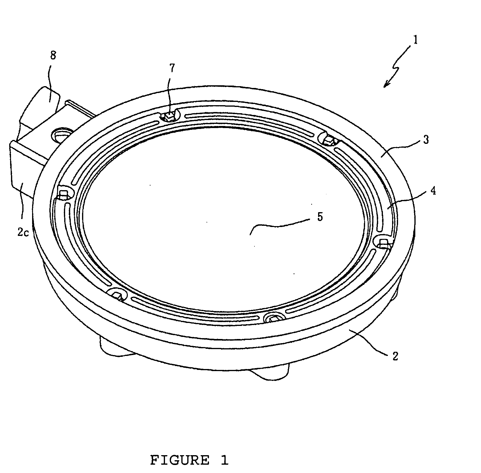
[0037]Below, preferred embodiments of the present invention will be explained with reference to the attached drawings. An electronic percussion instrument 1 according to an example embodiment of the present invention is an electronic percussion instrument referred to as an “electronic drum” that is played using sticks and the like, provided with sensors that detect vibrations due to hits. Musical note equipment (not shown) controls a sound source based on the signals detected by the sensors and is designed so as to generate musical notes or sounds in proportion to the hits. The musical notes or sounds are output from speaker equipment via amplifier equipment.

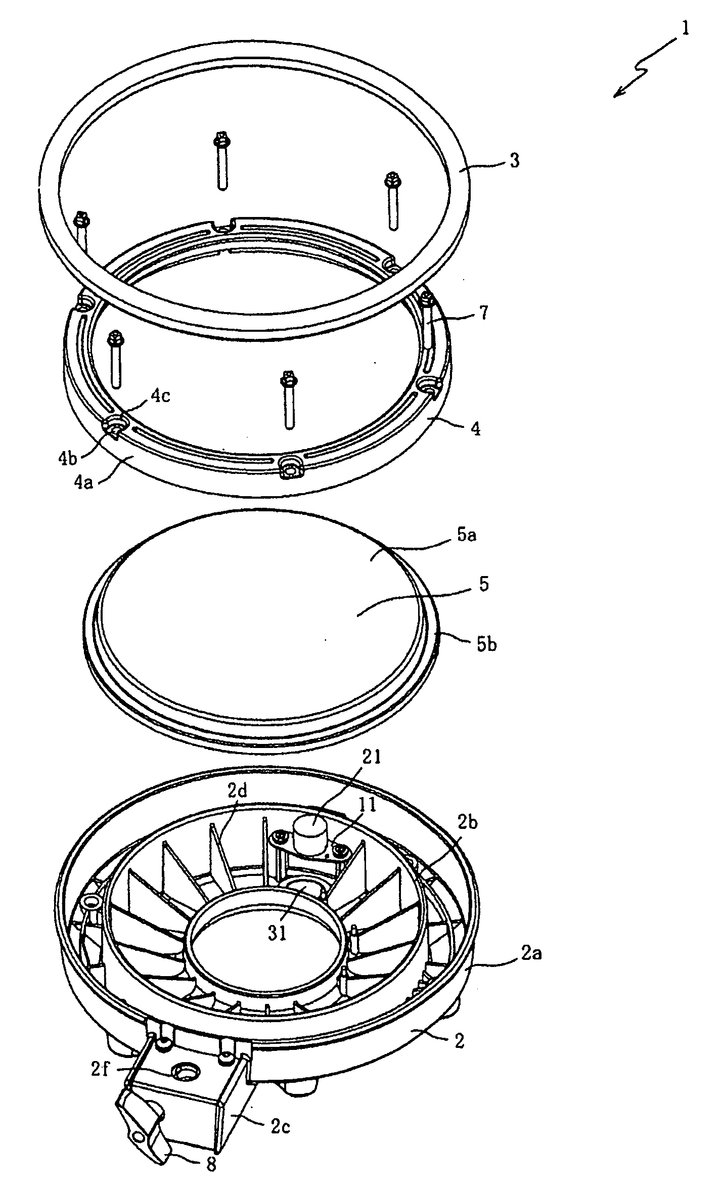
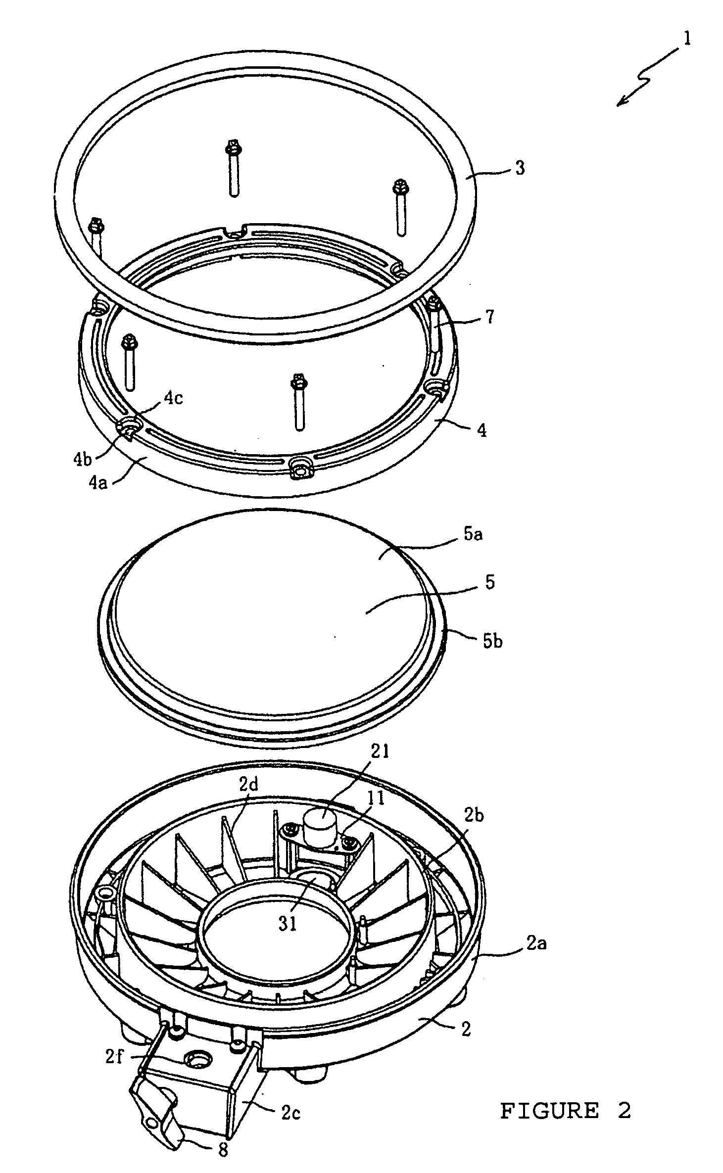
[0038]FIG. 1 is an external perspective view of an electronic percussion instrument 1 according to one embodiment of the present invention. The exterior of electronic percussion instrument 1, as shown in FIG. 1, is provided with a body part 2, a rim cover 3, a hoop 4, and a head 5.

[0039]FIG. 2 is an exploded perspective view tha...


PUM


Abstract

An electronic percussion instrument that detects vibrations due to a hit and outputs a corresponding signal where the head of the instrument is held in place independent of a rim part. The independence stops vibrations originating from a hit of the rim from traveling to the head and interfering with the proper signal detection of hits to the head part.

Description

CROSS-REFERENCE TO RELATED PATENT APPLICATIONS[0001]This application claims priority to Japanese patent application No. 2006-076441 (filed on Mar. 22, 2006 in Japan), which was assigned to the applicant and is incorporated herein by reference, in its entirety.BACKGROUND OF THE INVENTION[0002]1. Field of the Invention[0003]Embodiments of the present invention relate to electronic percussion instruments, in particular to an electronic percussion instrument that has a rim part separate from a hoop part that imparts tension to the head and a method of arranging the rim part, hoop part, and head part forming an electronic percussion instrument.[0004]2. Related Art[0005]Various electronic percussion instruments have been proposed, including electronic drums based on acoustic drums. These electronic drums have been formed such that a sensor detects the vibrations occurring when the electronic drum is hit. The detected signal from the sensor controls a sound source that forms musical notes ...

Claims


Application Information

Patent Timeline
Patent Type & Authority Applications(United States)
IPC IPC(8): G10H3/00
CPCG10D13/024G10H2230/301G10H2220/525G10H3/146G10D13/02G10D13/26
Inventor MATSUYUKI, HIROTAKAYOSINO, KIYOSHIKATSUDA, MASATO
Owner ROLAND CORP
Why Eureka
Try Eureka