Brake shoe
a technology for brake shoes and brake pedals, applied in brake types, friction linings, brake pedals, etc., can solve the problems of high dampening of humming, squeaking and crumpling noises, and achieve the effect of keeping the development of noise and the transmission of vibrations onto the steering wheel or the brake pedal continuously low
- Summary
- Abstract
- Description
- Claims
- Application Information
AI Technical Summary
Benefits of technology
Problems solved by technology
Method used
Image
Examples
first embodiment
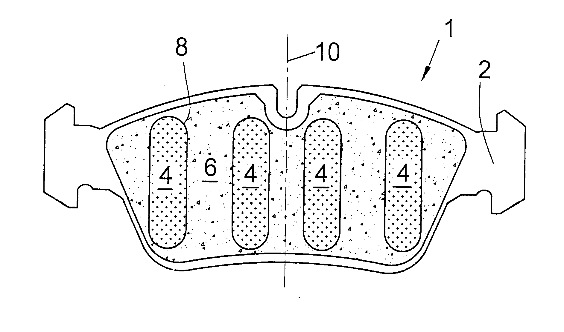
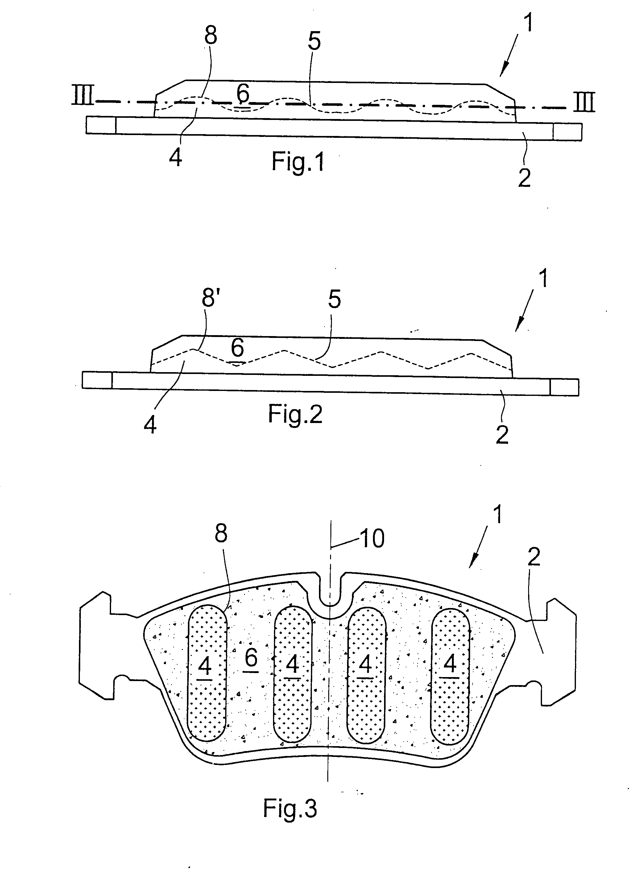
[0044] a brake shoe 1, shown in FIG. 1, comprises a metallic carrier plate 2 having first arranged thereon an intermediate layer 4 functioning as a dampening layer between the friction lining 6 and the carrier plate 2.
[0045] The intermediate layer4 comprises, on the side thereof facing towards the friction lining 6, a three-dimensional surface structure 5 provided with projections 8 engaging the friction lining 6. The friction lining 6 is correspondingly adapted to the surface contour 5 of the intermediate layer 4 and comprises a friction material of the usual type.
[0046] In FIG. 1, the surface structure 5 of that side of the intermediate layer 4 which is facing towards the friction lining 6 is indicated by the interrupted line. Thus, the embodiment according to FIG. 1 presents a three-dimensional surface structure of the intermediate layer 4 which, when viewed in cross-section, has a wave shape. FIG. 3 is a sectional view taken along the line III-III in FIG. 1, from which it can b...
third embodiment
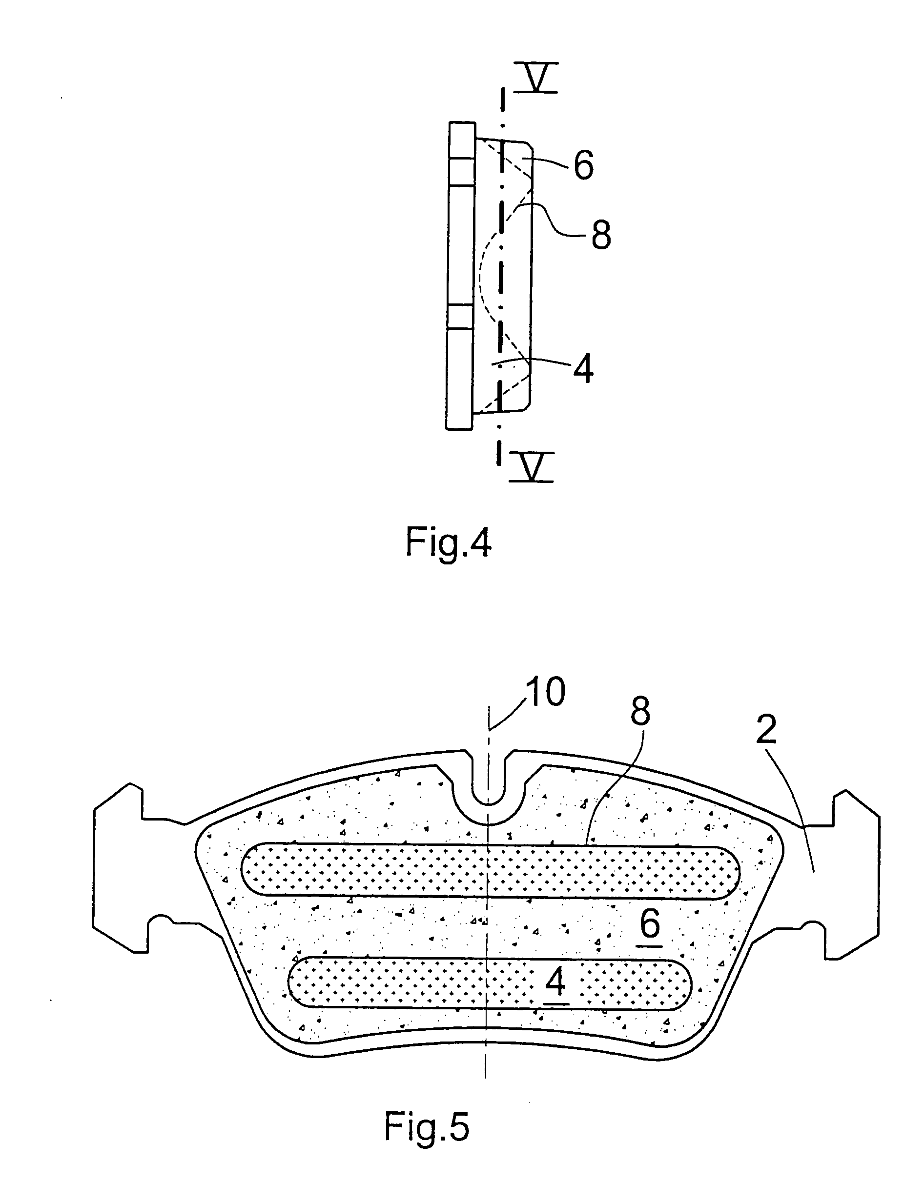
[0050]FIG. 4 shows a third embodiment comprising projections 8 having sinusoidal or triangular shapes as viewed in cross section, with the projections, in contrast to the embodiment according to FIG. 3, extending in a transverse direction relative to the radial axis of symmetry 10 of brake shoe 1. This can be best seen in FIG. 5 which is a sectional view taken along the line V-V in FIG. 4.
fourth embodiment
[0051] Illustrated in FIG. 6 is a fourth embodiment wherein the surface structure 5 extends at an inclination relative to the carrier plate 2, thus forming a wedge-shaped intermediate layer 4 with three-dimensional surface structure 5.
[0052] In this arrangement, the projections of the surface structure 5 can have any one of the various cross-sectional shapes illustrated in FIG. 11. The surface structure 5 can be inclined about one or two axes. For instance, the inclination can be adjusted relative to the radial axis of symmetry 10 and / or an axis which is orthogonal to this axis of symmetry 10 and parallel to the carrier plate 2.
[0053] The embodiment according to FIGS. 7 and 8 presents a surface structure 5 comprising dot-shaped projections 8″.
[0054]FIG. 7 is a sectional view taken along the line VII-VII in FIG. 8, and FIG. 8 is a sectional view taken along the line VIII-VIII in FIG. 7.
[0055] The embodiment according to FIG. 9 presents an asymmetrical arrangement of the projection...
PUM
| Property | Measurement | Unit |
|---|---|---|
| thickness | aaaaa | aaaaa |
| stiffness | aaaaa | aaaaa |
| shape | aaaaa | aaaaa |
Abstract
Description
Claims
Application Information
 - R&D
- Intellectual Property
- Life Sciences
- Materials
- Tech Scout
- Unparalleled Data Quality
- Higher Quality Content
- 60% Fewer Hallucinations
Browse by: Latest US Patents, China's latest patents, Technical Efficacy Thesaurus, Application Domain, Technology Topic, Popular Technical Reports.
© 2025 PatSnap. All rights reserved.Legal|Privacy policy|Modern Slavery Act Transparency Statement|Sitemap|About US| Contact US: help@patsnap.com


