Edging and trenching blade

a technology of trenching blades and blades, which is applied in the field of edging blades, can solve the problems of thin cutting of blades, and achieve the effects of avoiding clogging of the cover and jamming of the blade, efficient edging or trenching operation, and convenient use in the machin

Active Publication Date: 2007-10-25
BLADE ENTERPRISES
View PDF46 Cites 0 Cited by
  • Summary
  • Abstract
  • Description
  • Claims
  • Application Information

AI Technical Summary

Benefits of technology

[0014] In operation of the blade, the second edge enters the ground progressively nearer to the second corner until the second corner enters the ground. The second edge may be sharpened or may be a flat edge of the rectangular plate. Continued rotation of the blade causes the first teeth to enter the ground next. A corner tooth at the first corner enters the ground first. The first teeth extend in the second direction. If the first teeth include the inner and outer teeth spaced different distances from the second surface, the inner first tooth penetrates the ground at a peripheral portion up to an extent of the inner distance. Then, the outer first tooth enters the ground at a peripheral portion up to an extent of the greater outer distance. Because the teeth are formed of bent tabs of the thin rectangular plate, only a thin surface of each of the inner and outer first teeth, having a thickness of the plate, along with short curved portions of the teeth, are exposed to the ground. This minimizes resistance of penetration of the blade into the ground while resulting in a wider cut compared to typical rectangular-plate edging blades.
[0015] As the blade continues generally vertical, clockwise rotation, the first edge enters the ground progressively nearer to the third corner and then the third corner enters the ground. The third corner enters the ground approximately 180° from where the second corner enters the ground. The first edge may be sharpened or may be a flat edge of the rectangular plate near the second end. Continued clockwise rotation of the blade causes the second teeth to enter the ground next. A corner tooth at the fourth corner enters the ground first. The corner tooth enters the ground approximately 180° from where the other corner tooth enters the ground. The second teeth extend in the first direction. If the second teeth include the inner and outer teeth, the inner second tooth enters the ground first at a peripheral surface up to an extent of the inner distance. Then, the outer second tooth enters the ground at a peripheral surface up to an extent of the greater outer distance. Because the teeth are formed of bent tabs of the plate, only a thin surface of each of the inner and outer teeth, having a thickness of the plate, along with short curved portions of the teeth, are exposed to the ground. This minimizes resistance of penetration of the blade into the ground while resulting in a wider cut compared to typical rectangular-plate edging blades. Rotation of the blade in this manner forms a trench in the ground having a width equal to the distance between the outer peripheral surfaces of the outer first and second teeth.
[0018] The inventive blade is advantageously suitable as an edging or trenching blade for edging or cutting a trench into the ground and through grass, sod, turf, leaves, thatch and the like located on or in the ground. The blade can be used for edging along objects including landscaping, sidewalks or driveways, or for trenching, for example, cutting trenches for laying wire or conduit below the ground. In addition, multiple blades can be mounted to a shaft, which facilitates use in a machine for making wide cuts or tilling of the ground.
[0019] Each inventive blade is able to cut a wider trench into the ground than current edging blades that are formed of a rectangular plate without teeth. The inventive blade cuts through grass cleaner than the typical rectangular-plate edging blade. In addition, the inventive teeth, extending to either side near each end of the blade, prevent a common problem with rectangular-plate edging blades whereby the blade cover is clogged with grass, leaves or other matter thrown upwardly by the blade. The inventive teeth enable the blade to throw material to the sides of the blade rather than upwardly into the cover. This avoids clogging of the cover and jamming of the blade and a more efficient edging or trenching operation compared to conventional blades.

Problems solved by technology

One limitation is that the rotating tip of the blade makes a thin cut into the grass having a width of the blade.
One problem with existing edging blades is that the soil or grass is thrown up into a safety cover over the blade, which tends to lead to clogging.

Method used


Image

  • Edging and trenching blade
  • Edging and trenching blade
  • Edging and trenching blade

Examples


Embodiment Construction

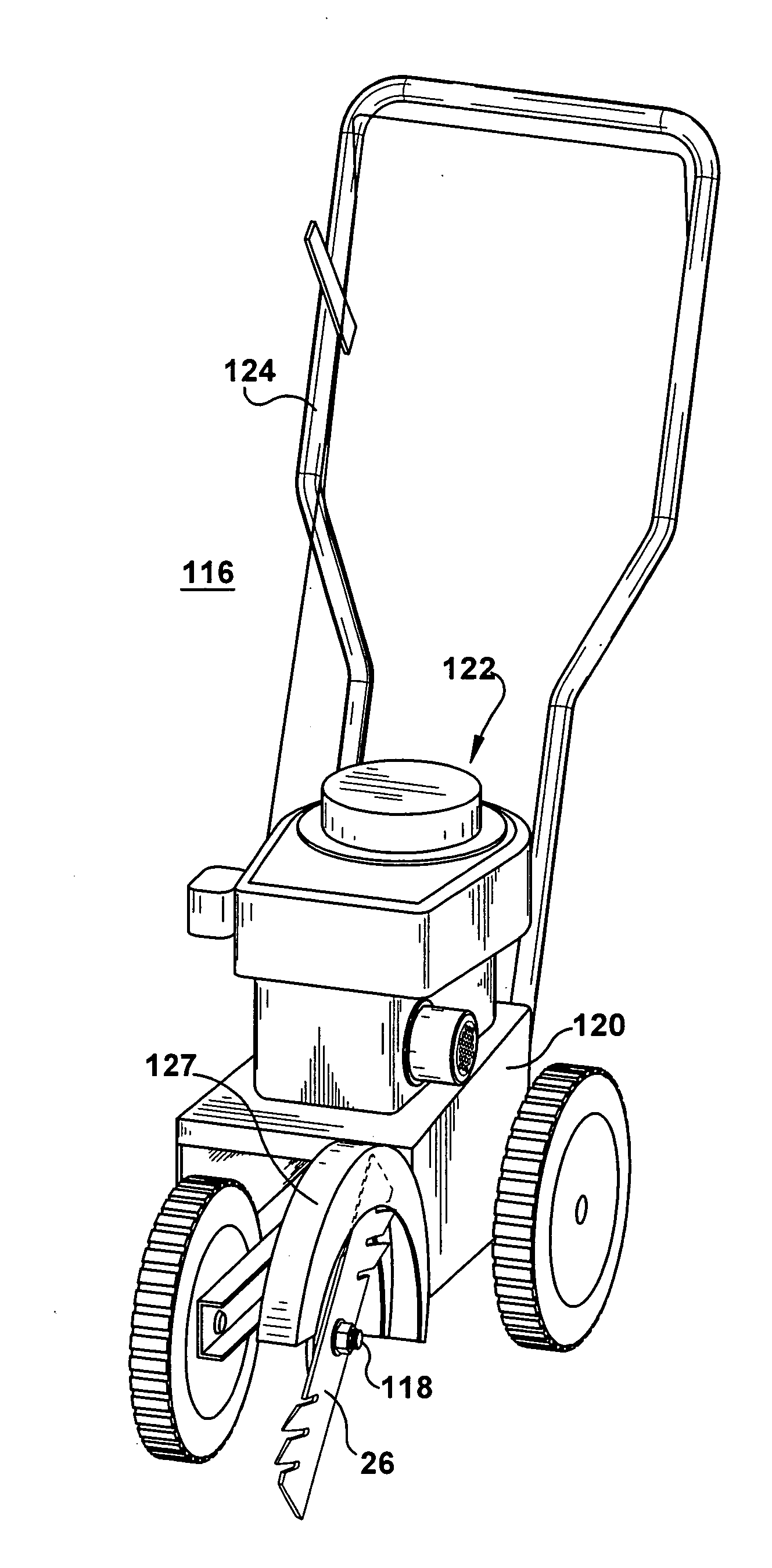
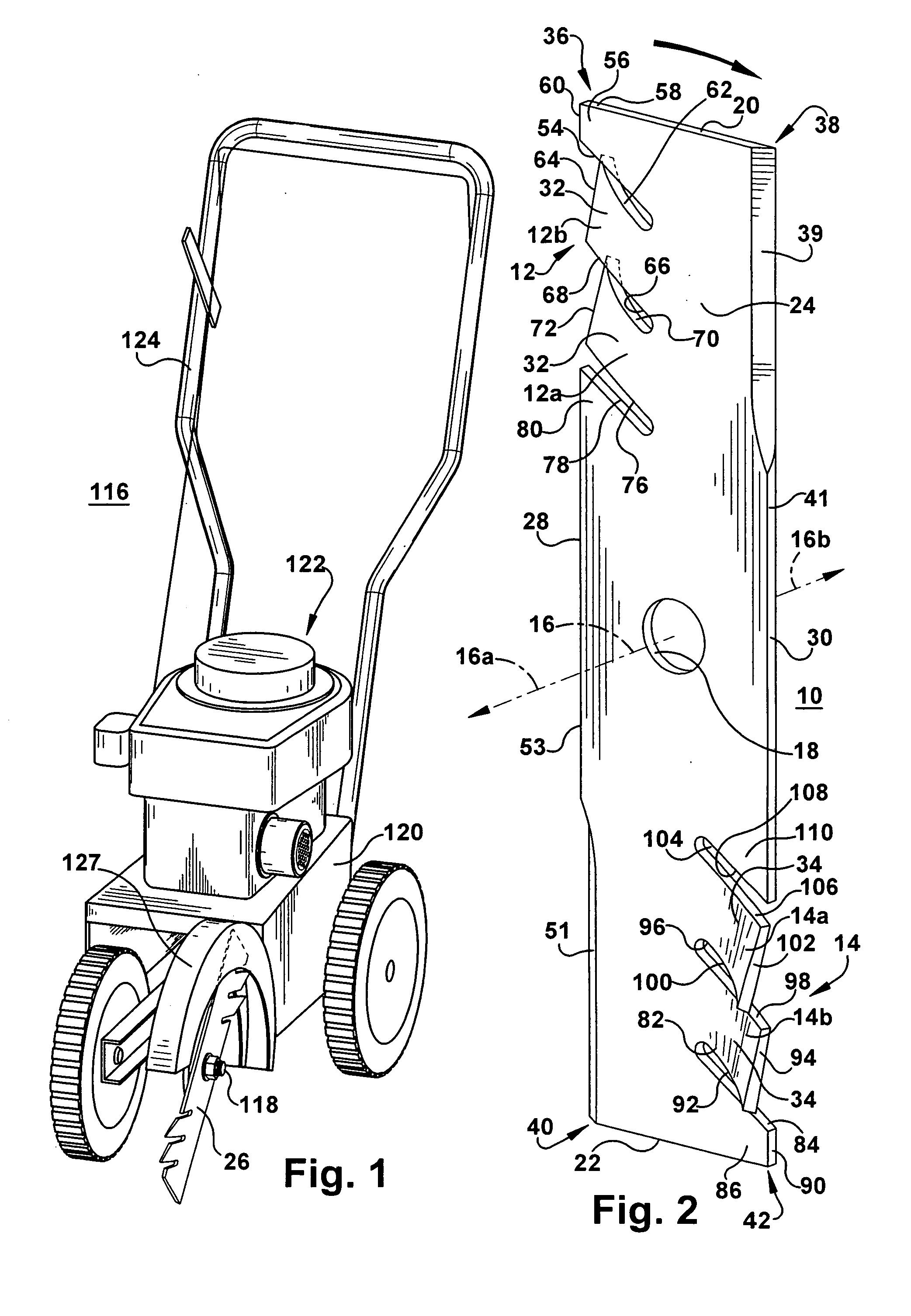
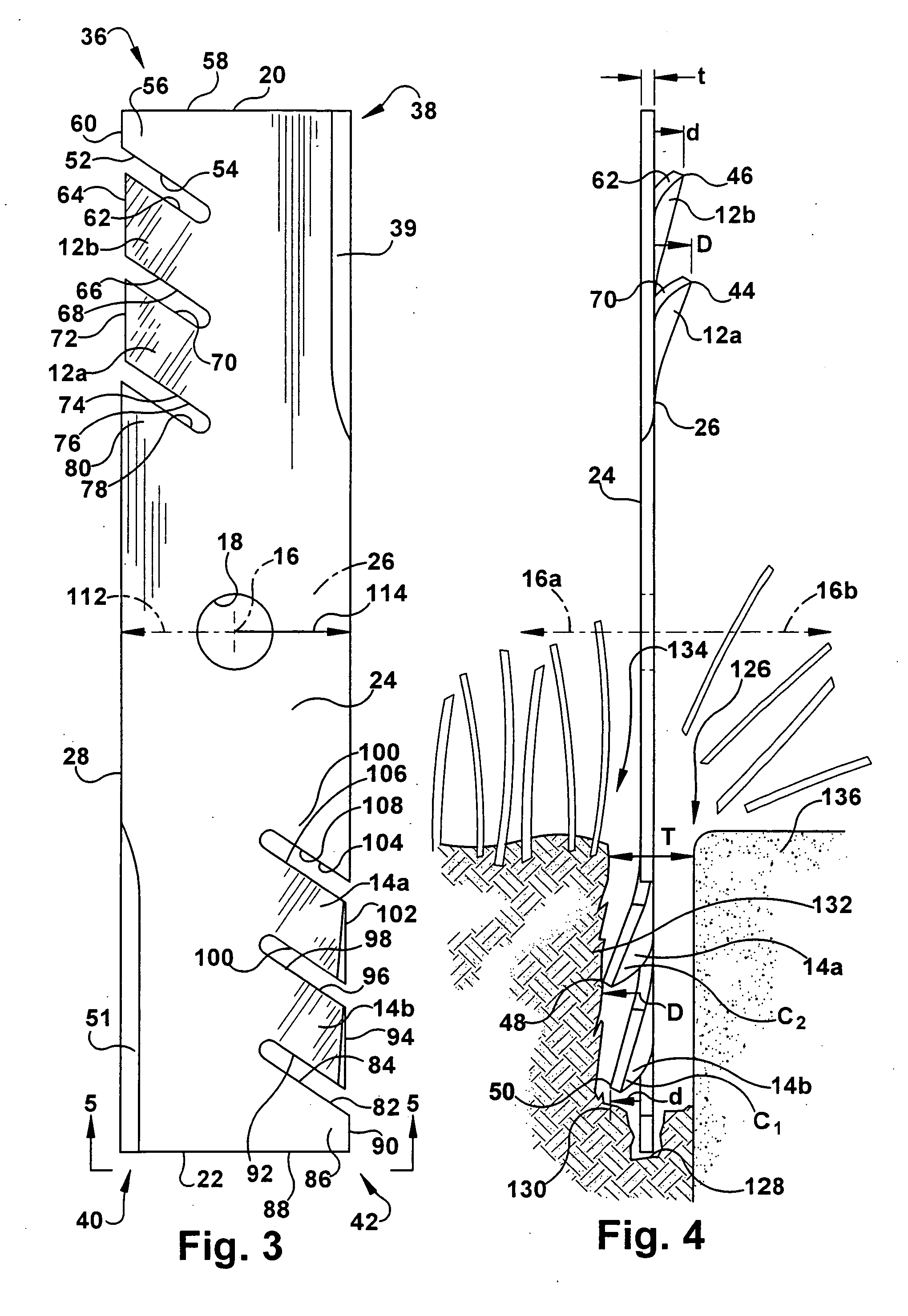
[0028] Referring to the drawings, the present invention features a generally rectangular shaped blade 10 including first and second sets of teeth 12, 14 near opposing ends of the blade. The blade has a rotational axis 16 and is adapted to penetrate a surface to be cut. The axis extends in a first axis direction 16a (e.g., outwardly to the left from the left side of the blade) and in a second axis direction 16b (e.g., outwardly to the right from the right side of the blade). The first and second axis directions 16a, 16b are opposite, i.e., disposed 180° apart from each other. Referring to FIGS. 2 and 4, the first teeth 12 extend to the right and are referred to as right teeth and the second teeth 14 extend to the left and are referred to as left teeth. A central opening 18 is formed in the blade having the axis of rotation at its center. The opening can be circular, square or other suitable shape. The blade may be formed of any suitably hard and impact resistant material such as meta...


PUM


Abstract

The invention features an elongated blade having at least one first tooth near a first end extending in one direction and at least one second tooth near a second end extending in the opposite direction. The body of the blade can be a generally rectangular plate. There can be at least two first and second teeth. The blade can include four corners, wherein at the first end the first teeth are formed in the first edge and at the second end the second teeth are formed in the second edge. Edges of the blade can be formed without teeth near two corners and can be sharpened or not. The teeth may extend different distances from the blade. The blade cuts into a surface. In one application, the blade is used for edging or trenching and is rotated generally vertically so as to penetrate the ground and any material on or in the ground such as grass, sod, turf, leaves, thatch and the like. The invention also features devices used to power a shaft on which one or more of the blades are mounted, such as edging or trenching machines.

Description

FIELD OF THE INVENTION [0001] The present invention is directed to blades for cutting into surfaces and, in particular, to trenching and edging blades for cutting into the ground. BACKGROUND OF THE INVENTION [0002] In the landscaping business a common task is to edge around landscaping, sidewalks or driveways. This can be carried out by a machine known as an edger having a blade rotated vertically by a motor driven shaft on which it is mounted. The blade used in conventional edgers is usually rectangular bar stock that can have sharpened edges near each end. One limitation is that the rotating tip of the blade makes a thin cut into the grass having a width of the blade. This is followed with cleanup by hand to remove the grass that overhangs the cut. Each blade can have multiple sections (e.g., four perpendicular rectangular cutting sections rather than just a rectangular piece of bar stock). One problem with existing edging blades is that the soil or grass is thrown up into a safet...

Claims


Application Information

Patent Timeline
Patent Type & Authority Applications(United States)
IPC IPC(8): E21B7/14
CPCA01D34/84
Inventor BARAN, GREGORY
Owner BLADE ENTERPRISES
Why Eureka
Try Eureka