
Eureka
For R&D, Eureka makes reading and utilizing patents & technical documents easy.
Eureka AIR
Designed for self-driven R&D workflows. Generate viable solutions, solve complex R&D challenges, empower your innovation with AI.

Eureka Materials
Designed for material experts only. Revolutionize your material R&D, from search, analyze, to developing new materials.

TechResearch
Generate reliable direction feasibility study reports for your R&D in just a few steps.

TechSeek
Discover and master advanced knowledge NOW. Basics, ideas, possibilities, all at once.

TechMind
As an expert in R&D Theories, TechMind can generates customized viable solutions instantly.

TechRisk
Analyze your overall solution with one click, know your potential R&D risks in advance.

TechMonitor
Get weekly tech updates, stay abreast of the latest tech innovations and key insights.
Synchronization of precursor pulsing and wafer rotation
- Summary
- Abstract
- Description
- Claims
- Application Information
AI Technical Summary
Problems solved by technology
Method used
Image

Examples
Embodiment Construction
[0016] The present invention describes a method of uniformly depositing films within a batch processing chamber. A particularly good batch processing chamber that can be used to practice the invention is described in U.S. patent application Ser. No. 11 / 249,555, filed Oct. 13, 2005, which is hereby incorporated by reference in its entirety. The invention is illustratively described below with reference to a FLEXSTAR™ system, available from Applied Materials, Inc., Santa Clara, Calif.
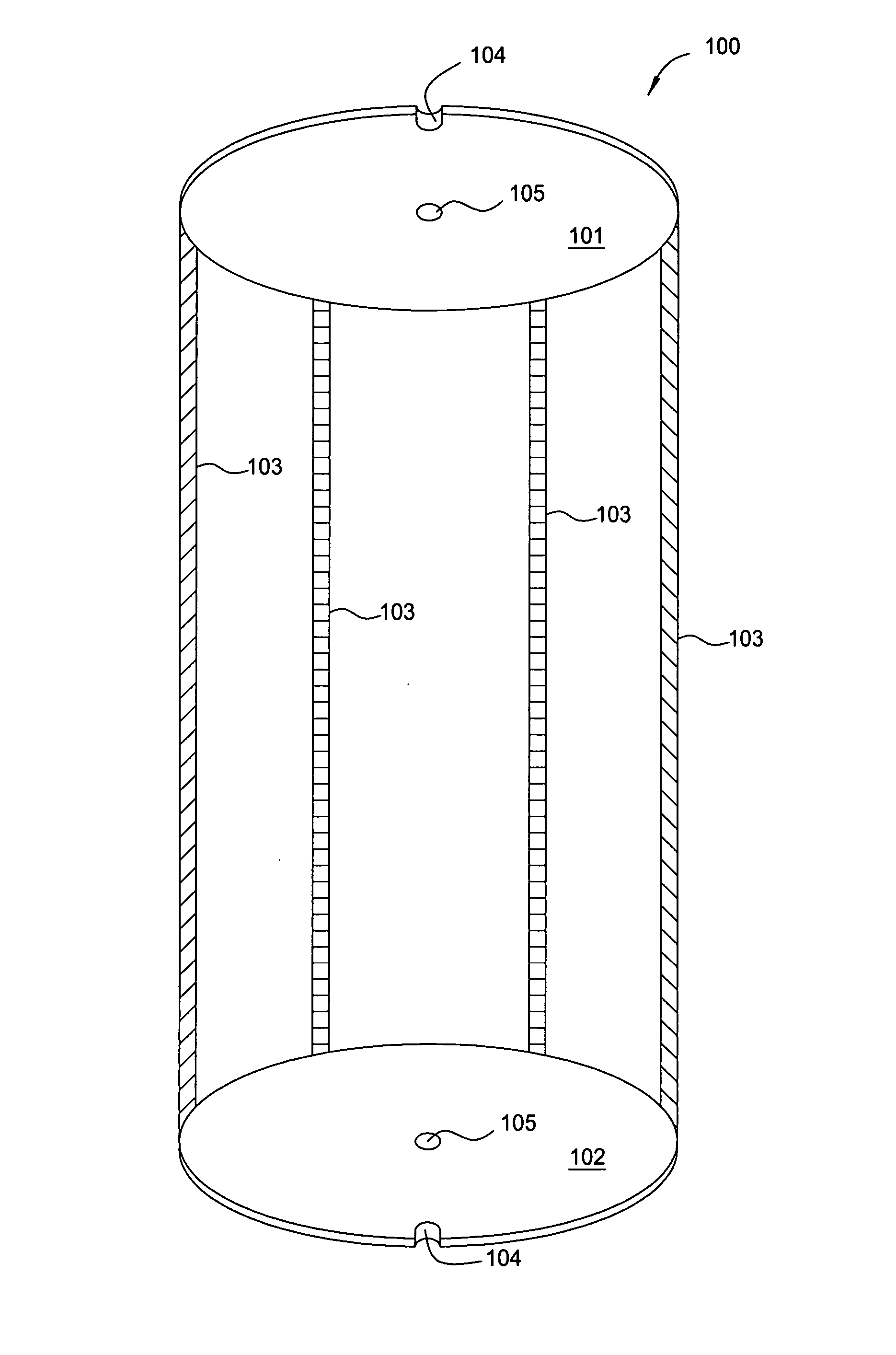
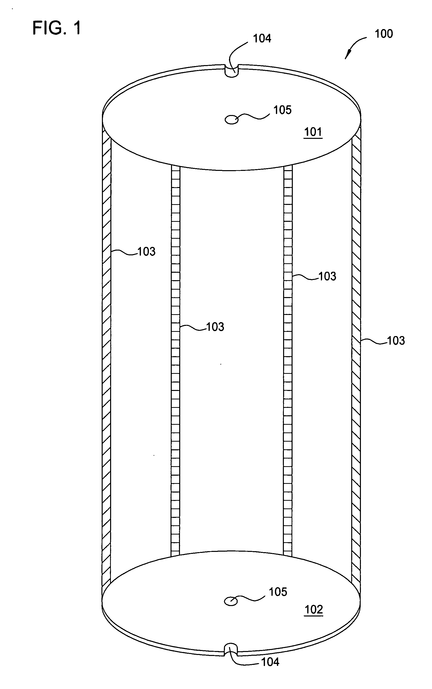
[0017]FIG. 1 is a schematic drawing of a substrate boat used in batch processing chambers. Other examples of substrate boats that can be used in batch processing are described in U.S. patent application Ser. No. 11 / 216,969, filed Aug. 31, 2005, which is hereby incorporated by reference in its entirety. FIG. 1 shows a substrate boat 100 that can be used in the present invention. The substrate boat 100 has a cap portion 101 and a base portion 102. The cap portion 101 and the base portion 102 are connected ...
PUM
| Property | Measurement | Unit |
|---|---|---|
| Time | aaaaa | aaaaa |
| Height | aaaaa | aaaaa |
| Perimeter | aaaaa | aaaaa |
Abstract
Description
Claims
Application Information
 - R&D Engineer
- R&D Manager
- IP Professional
- Industry Leading Data Capabilities
- Powerful AI technology
- Patent DNA Extraction
Browse by: Latest US Patents, China's latest patents, Technical Efficacy Thesaurus, Application Domain, Technology Topic, Popular Technical Reports.
© 2024 PatSnap. All rights reserved.Legal|Privacy policy|Modern Slavery Act Transparency Statement|Sitemap|About US| Contact US: help@patsnap.com