
Methods and systems for compensating for alien crosstalk between connectors

a technology of alien crosstalk and connectors, applied in the direction of line-transmission details, coupling device connections, instruments, etc., can solve the problems of alien crosstalk being a threat to shielded network systems, ungrounded shields acting as antennae for electromagnetic interference, and undesirable use, so as to minimize alien crosstalk, minimize alien crosstalk, and efficiently and accurately propagate high-speed data signals

Inactive Publication Date: 2007-11-08
COMMSCOPE TECH LLC
View PDF1 Cites 0 Cited by
  • Summary
  • Abstract
  • Description
  • Claims
  • Application Information

AI Technical Summary

Benefits of technology

This solution effectively minimizes alien crosstalk between connectors, ensuring high-speed data signal integrity and compliance with standards without the need for costly shielding or grounding, maintaining signal quality in unshielded cabling systems.

Problems solved by technology

Although other types of connectors have achieved levels of isolation that may combat the alien crosstalk produced by high-speed transmission signals, these types of connectors have shortcomings that make their use undesirable in many communications systems, such as LAN communities.
For example, shielded connectors exist that may achieve adequate levels of isolation to protect high-speed signal integrity, but these types of shielded connectors typically use a ground connection or can be used only with shielded cabling, which costs considerably more than unshielded cabling.
Further, inasmuch as ground connections may become faulty, shielded network systems run the risk of the ungrounded shields acting as antennae for electromagnetic interference.
Conventional network connectors cannot effectively and accurately transmit high-speed data signals.
Specifically, the conventional connectors for use in unshielded cabling networks do not provide adequate levels of compensation or isolation from alien crosstalk.

Method used


Image

  • Methods and systems for compensating for alien crosstalk between connectors
  • Methods and systems for compensating for alien crosstalk between connectors
  • Methods and systems for compensating for alien crosstalk between connectors

Examples


second embodiment

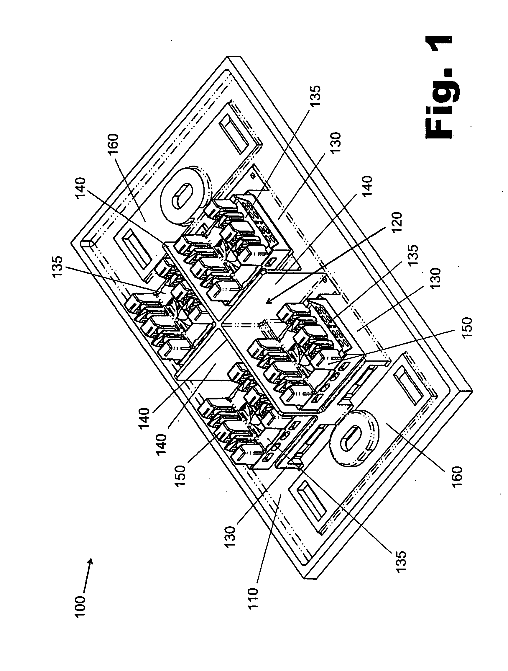
[0069]FIG. 3 is a perspective view of the jack assembly 100 of FIG. 1. The jack assembly 100-1 shown in FIG. 3 includes a shield structure 120-1. The shield structure 120-1 includes the features of the shield structure 120 and further includes a number of outer shield sections 340 positioned along the outer edges of the jacks 135 to shield the jacks 135 from alien crosstalk generated by sources external of the jack assembly 100-1. For example, the outer shield sections 340 can isolate the jacks 135 of the jack assembly 100-1 from alien crosstalk generated by external jacks of adjacent jack assemblies, which may lack a shield structure 120-1. The jacks 135 positioned generally lateral from the jacks 135 of the jack assembly 100-1 are of particular concern. In FIG. 3, the outer shield sections 340 are positioned along each outer edge of the jacks 135, forming a perimeter of outer shield sections 340 about the jacks 135. The outer shield sections 340 should form at least a partial peri...

third embodiment

[0071]FIG. 5 shows a perspective view of the jack assembly 100 of FIG. 1. FIG. 5 shows a jack assembly 100-2 that includes a shield structure 120-2 inserted between the jack receptacles 130 to separate the received jacks 135. The shield structure 120-2 includes the same features of the shield structure 120. Further, the shield structure 120-2 can be configured to fittingly couple to the frame 110 to separate the adjacent jacks 135. Specifically, the shield structure 120-2 includes shield sections 140-2 configured to facilitate an easy insertion and / or removal of the shield structure 120-2 between the jacks 135.

[0072] The shield sections 140-2 can be arranged in wide variety of ways such that they can be fittingly coupled to the frame 110 and separate the jacks 135. As shown in FIG. 5, the shield sections 140-2 can be joined together by a joining member 510 such that the shield sections 140-2 and the joining member 510 form a generally U-shaped structure.

[0073] The joining member 51...

fourth embodiment

[0077]FIG. 7 is a perspective view of the jack assembly 100 of FIG. 1. The jack assembly 100-3 shown in FIG. 7 includes a number of shield structures 120-3 positioned to isolate the received jacks 135. The shield structure 120-3 can be fixedly coupled to the jack 135 or to the jack receptacle 130 such that the shield structure 120-3 forms a perimeter about the jack 135. In FIG. 7, the shield structure 120-3 forms a perimeter about the lateral sides of the jack 135, and is thereby positioned to act as a barrier to alien crosstalk on the lateral sides of the jack 135. When the adjacent jacks 135 are each fitted with the shield structure 120-3, the shield structure 120-3 reduces alien crosstalk between the adjacent jacks 135. Other embodiments of the shield structure 120-3, some of which will be discussed below, form only a partial perimeter about the jack 135.

[0078]FIG. 8 shows a perspective view of the shield structure 120-3 of FIG. 7. The shield structure 120-3 shown in FIG. 8 can i...


PUM


Abstract

The present invention relates to methods and systems for minimizing alien crosstalk between connectors. Specifically, the methods and systems relate to isolation and compensation techniques for minimizing alien crosstalk between connectors for use with high-speed data cabling. A frame can be configured to receive a number of connectors. Shield structures may be positioned to isolate at least a subset of the connectors from one another. The connectors can be positioned to move at least a subset of the connectors away from alignment with a common plane. A signal compensator may be configured to adjust a data signal to compensate for alien crosstalk. The connectors are configured to efficiently and accurately propagate high-speed data signals by, among other functions, minimizing alien crosstalk.

Description

RELATED APPLICATIONS [0001] The present application is related to applications entitled “CABLE WITH OFFSET FILLER” (U.S. Ser. No. 10 / 746,800) and “CABLE UTILIZING VARYING LAY LENGTH MECHANISMS TO MINIMIZE ALIEN CROSSTALK” (U.S. Ser. No. 10 / 746,757), each filed Dec. 26, 2003, and each of which is incorporated by reference in its entirety. The present application is also related to applications entitled “METHODS AND SYSTEMS FOR MINIMG ALIEN CROSSTALK BETWEEN CONNECTORS” and “METHODS AND SYSTEMS FOR POSITIONING CONNECTORS TO MINDS ALIEN CROSSTALK”, each filed on the same date as the present application.BACKGROUND OF THE INVENTION [0002] The present invention relates to methods and systems for minimizing alien crosstalk between connectors. Specifically, the methods and systems relate to isolation and compensation techniques for minimizing alien crosstalk between connectors for use with high-speed data cabling. [0003] In the field of data communications, communications networks typically...

Claims


Application Information

Patent Timeline
Patent Type & Authority Applications(United States)
IPC IPC(8): H04M1/76G01R27/00H01R13/719H04B3/32H04M1/00
CPCH01R13/518H01R13/6464H04B3/32H01R13/719
Inventor HAMMOND, BERNARD JR.
Owner COMMSCOPE TECH LLC
Features
  • Generate Ideas
  • Intellectual Property
  • Life Sciences
  • Materials
  • Tech Scout
  • Unparalleled Data Quality
  • Higher Quality Content
  • 60% Fewer Hallucinations
Learn More