
Cable with offset filler

a filler and cable technology, applied in the direction of cables, insulated conductors, conductors, etc., can solve the problems of limiting the speed of data flow between communications devices, signal becomes more sensitive to undesirable influences from cables, and the integrity of signals is jeopardized, so as to achieve efficient and accurate propagation of high-speed data signals

Inactive Publication Date: 2005-08-04
COMMSCOPE TECH LLC
View PDF99 Cites 12 Cited by
  • Summary
  • Abstract
  • Description
  • Claims
  • Application Information

AI Technical Summary

Benefits of technology

The present invention is about cables made of twisted conductor pairs, which are used for high-speed data communications. These cables have twisted pairs of conductors that are surrounded by insulation. The conductors are twisted along a longitudinal axis. The invention includes at least two twisted pairs and a filler. The cables are positioned along parallel axes and are designed to efficiently and accurately transmit high-speed data signals. The invention also aims to limit impedance deviations, signal attenuation, and alien crosstalk along a predefined distance.

Problems solved by technology

Consequently, the data cables of typical communications networks, such as local area network (LAN) communities, limit the speed of data flow between communications devices.
If cables do not at least satisfy these standards, the integrity of their signals is jeopardized.
In general, as the speed of a data signal increases, the signal becomes more sensitive to undesirable influences from the cable, such as the effects of impedance, attenuation, and crosstalk.
Any deviation from this impedance match at any point along the cable will result in reflection of part of the transmitted signal back towards the transmission end of the cable, thereby degrading the transmitted signal.
This degradation due to signal reflection is known as return loss.
Greater variations in impedance will result in worse signal degradation.
However, the same ranges of impedance variations jeopardize the integrity of high-speed signals because the undesirable effects of the impedance variations are accentuated when higher speed signals are transmitted.
A signal, if attenuated too much, becomes unrecognizable to a receiving device.
The material of the jacket also affects attenuation, especially when a cable does not contain internal shielding.
Typical jacket materials used with conventional cables tend to have higher dielectric constants, which can contribute to greater signal loss.
These fields are also known as electrical noise or interference because the fields can undesirably affect the signals being transmitted along other proximate conductors.
This further degrades the ability of pairs to resist noise migration.
The conventional cables are unable to accurately and efficiently propagate the high-speed data signals that can be used by the emerging communications devices.
As mentioned above, the high-speed signals are more susceptible to signal degradation due to attenuation, impedance mismatches, and crosstalk, including alien crosstalk.
Moreover, the high-speed signals naturally worsen the effects of crosstalk by producing stronger interference fields about the signal conductors.
While conventional cables could overlook the effects of alien crosstalk when transmitting traditional data signals, the techniques used to control crosstalk within the conventional cables do not provide adequate levels of isolation to protect from cable to cable alien crosstalk between the conductor pairs of high-speed signals.
However, higher speed signals require increased bandwidth.
Consequently, conventional cables are not capable of overcoming the increased effects of powersum crosstalk that are produced by high-speed signals.
More importantly, conventional cables cannot overcome the increases of cable to cable crosstalk (alien crosstalk), which crosstalk is increased substantially because all of the twisted pairs of adjacent cables are potentially active.
Similarly, other conventional techniques are ineffective when applied to high speed communications signals.
However, by using more twisted pairs for transmissions, complex high-speed data signals generate more sources of noise, the effects of which are less predictable.
As a result, conventional methods used to cancel out the predictable effects of noise are no longer effective.
In regards to alien crosstalk, predictability methods are especially ineffective because the signals of other cables are usually unknown or unpredictable.
Moreover, trying to predict signals and their coupling effects on adjacent cables is impractical and difficult.
The increased effects of crosstalk due to high-speed signals pose serious problems to the integrity of the signals as they propagate along conventional cables.
Specifically, the high-speed signals will be unacceptably attenuated and otherwise degraded by the effects of alien crosstalk because conventional cables traditionally focus on controlling intra-cable crosstalk and are not designed to adequately combat the effects of alien crosstalk produced by high-speed signal transmissions.
However, conventional cables have not applied those techniques to the alien crosstalk between adjacent cables.
Further, suppressing alien crosstalk is more difficult than controlling intra-cable cross-talk because, unlike intra-cable crosstalk from known sources, alien crosstalk cannot be precisely measured or predicted.
Alien crosstalk is difficult to measure because it typically comes from unknown sources at unpredictable intervals.
As a result, conventional cabling techniques have not been successfully used to control alien crosstalk.
Moreover, many traditional techniques cannot be easily used to control alien crosstalk.
However, because alien crosstalk is difficult to measure or predict, known digital signal processing techniques cannot be cost effectively applied.
Thus, there exists an inability in conventional cables to control alien crosstalk.
In short, conventional cables cannot effectively and accurately transmit high-speed data signals.
Specifically, the conventional cables do not provide adequate levels of protection and isolation from impedance mismatches, attenuation, and crosstalk.
However, conventional cables of twisted conductor pairs typically provide isolations well short of the 60 dB needed at a signal frequency of 100 MHz, usually around 32 dB.
Consequently, conventional twisted pair cables cannot transmit the high-speed communications signals accurately or efficiently.
Although other types of cables have achieved over 60 dB of isolation at 100 MHz, these types of cables have shortcomings that make their use undesirable in many communications systems, such as LAN communities.
A shielded twisted pair cable or a fiber optic cable may achieve adequate levels of isolation for high-speed signals, but these types of cables cost considerably more than unshielded twisted pairs.

Method used


Image

  • Cable with offset filler
  • Cable with offset filler
  • Cable with offset filler

Examples


embodiment 240

[0071]FIG. 3 is a perspective view of one of the twisted pairs 240. As shown in FIG. 3, the cabled embodiment 240 includes two conductors 300 individually insulated by insulators 320 (also referred to as “insulation 320”). One conductor 300 and its surrounding insulator 320 are helically twisted together with the other conductor 300 and insulator 320 down a longitudinal axis. FIG. 3 further indicates the diameter (d) and the lay length (L) of the twisted pair 240. In some embodiments, the twisted pair 240 is shielded.

[0072] The twisted pair 240 can be twisted at various lay lengths. In some embodiments, the twisted pair's 240 conductors 300 are twisted generally longitudinally down said axis at a specific lay length (L). In some embodiments, the lay length (L) of the twisted pair 240 varies over a portion or all of the longitudinal distance of the twisted pair 240, which distance may be a predefined distance or length. By way of example only, in some embodiments, the predefined dist...

first embodiment

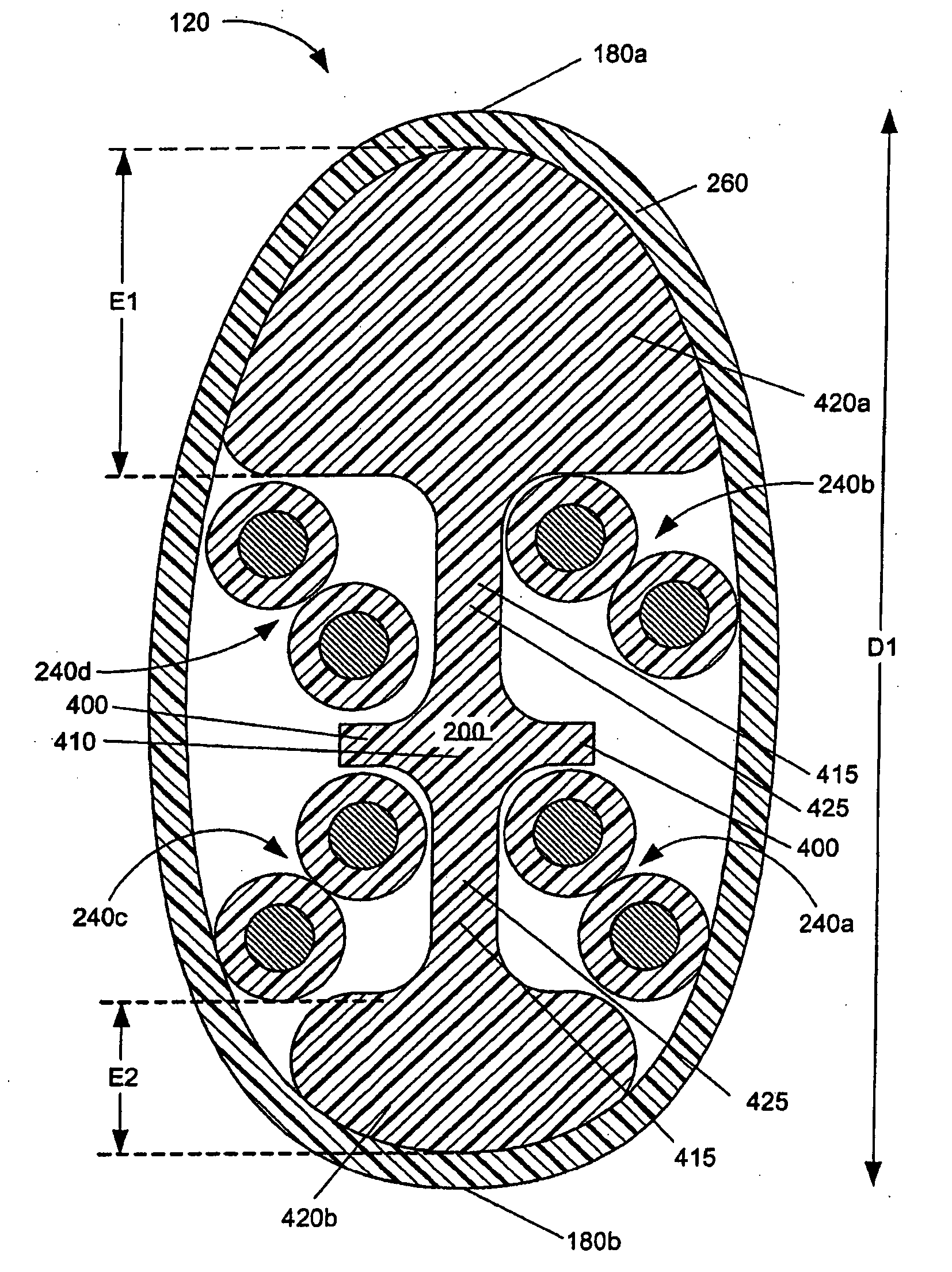
[0077]FIG. 4A shows an enlarged cross-sectional view of the cable 120 according to the invention. As shown in FIG. 4A, the jacket 260 surrounds the filler 200 and the twisted pairs 240a, 240b, 240c, 240d (collectively “the twisted pairs 240”) to form the cable 120. The twisted pairs 240a, 240b, 240c, 240d can be distinguished by having dissimilar lay lengths. While the twisted pairs 240a, 240b, 240c, 240d may have dissimilar lay lengths, they should be twisted in the same direction in order to minimize impedance mismatches, either all twisted pairs 240 having a right-hand twist or a left-hand twist. The lay lengths of the twisted pairs 240b, 240d are preferably similar, and the lay lengths of the twisted pairs 240a, 240c are preferably similar. In some embodiments, the lay lengths of the twisted pairs 240a, 240c are less than the lay lengths of the twisted pairs 240b, 240d. In such embodiments, the twisted pairs 240a, 240c can be referred to as the shorter lay length twisted pairs 2...

second embodiment

[0092] To illustrate examples of other embodiments of the cable 120, FIGS. 4B-4C show various different embodiments of the cable 120. FIG. 4B shows an enlarged cross-sectional view of a cable 120′ according to a The cable 120′ shown in FIG. 4B includes a filler 200′ that includes three legs 415 and three filler extensions 420 extending away from the legs 415 and beyond the cross-sectional areas of the twisted pairs 240. Each of the legs 415 includes the reference point 415. The filler 200′ can function in any of the ways discussed above in relation to the filler 200, including helping to distance adjacently positioned cables 120′ from one another.


PUM

PropertyMeasurementUnit
impedanceaaaaaaaaaa
frequencyaaaaaaaaaa
distanceaaaaaaaaaa

Abstract

The present invention relates to cables made of twisted conductor pairs. More specifically, the present invention relates to twisted pair communication cables for high-speed data communications applications. A twisted pair including at least two conductors extends along a generally longitudinal axis, with an insulation surrounding each of the conductors. The conductors are twisted generally longitudinally along the axis. A cable includes at least two twisted pairs and a filler. At least two of the cables are positioned along generally parallel axes for at least a predefined distance. The cables are configured to efficiently and accurately propagate high-speed data signals by, among other functions, limiting at least a subset of the following: impedance deviations, signal attenuation, and alien crosstalk along the predefined distance.

Description

RELATED APPLICATIONS [0001] The present utility application claims priority from the provisional application titled “CABLE WITH OFFSET FILLER” (Ser. No. 60 / 516,007) that was filed on Oct. 31, 20003, the contents of which are hereby incorporated herein in their entirety by reference. The present application is related to an application entitled “CABLE UTILIZING VARYING LAY LENGTH MECHANISMS TO MINIMIZE ALIEN CROSSTALK”, filed on the same date as the present application.BACKGROUND OF THE INVENTION [0002] The present invention relates to cables made of twisted conductor pairs. More specifically, the present invention relates to twisted pair cables for high-speed data communications applications. [0003] With the widespread and growing use of computers in communications applications, the ensuing volumes of data traffic have accentuated the need for communications networks to transmit the data at higher speeds. Moreover, advancements in technology have contributed to the design and deploy...

Claims


Application Information

Patent Timeline
Patent Type & Authority Applications(United States)
IPC IPC(8): H01B11/04H01B11/06
CPCH01B11/04Y10T29/49117H01B11/08H01B11/06
Inventor KENNY, ROBERTREEVES, STUARTFORD, KEITHGROSH, JOHN W.STUTZMAN, SPRINGANDERSON, ROGERWIEKHORST, DAVIDJOHNSTON, FRED
Owner COMMSCOPE TECH LLC
Features
  • Generate Ideas
  • Intellectual Property
  • Life Sciences
  • Materials
  • Tech Scout
  • Unparalleled Data Quality
  • Higher Quality Content
  • 60% Fewer Hallucinations
Learn More