Battery assembly with temperature control device

a temperature control device and battery pack technology, applied in the field of battery packs, can solve the problems of reducing the structural integrity reducing the product life or promoting premature failure of the battery pack, etc., and achieves the effects of cost saving, excellent retention, and efficient packaging characteristics

a temperature control device and battery pack technology, applied in the field of battery packs, can solve the problems of reducing the structural integrity reducing the product life or promoting premature failure of the battery pack, etc., and achieves the effects of cost saving, excellent retention, and efficient packaging characteristics

US20070259258A1Inactive Publication Date: 2007-11-08ENERDEL

Image

  • Battery assembly with temperature control device
  • Battery assembly with temperature control device
  • Battery assembly with temperature control device

Examples


Embodiment Construction

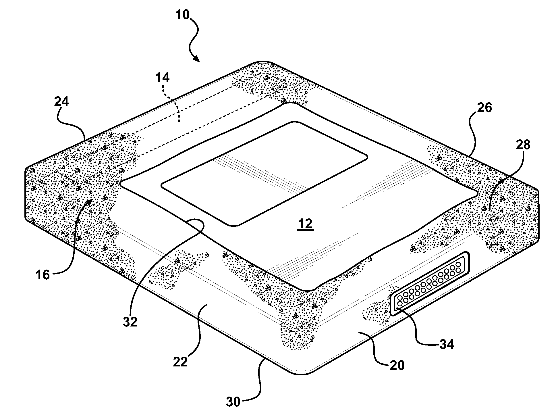
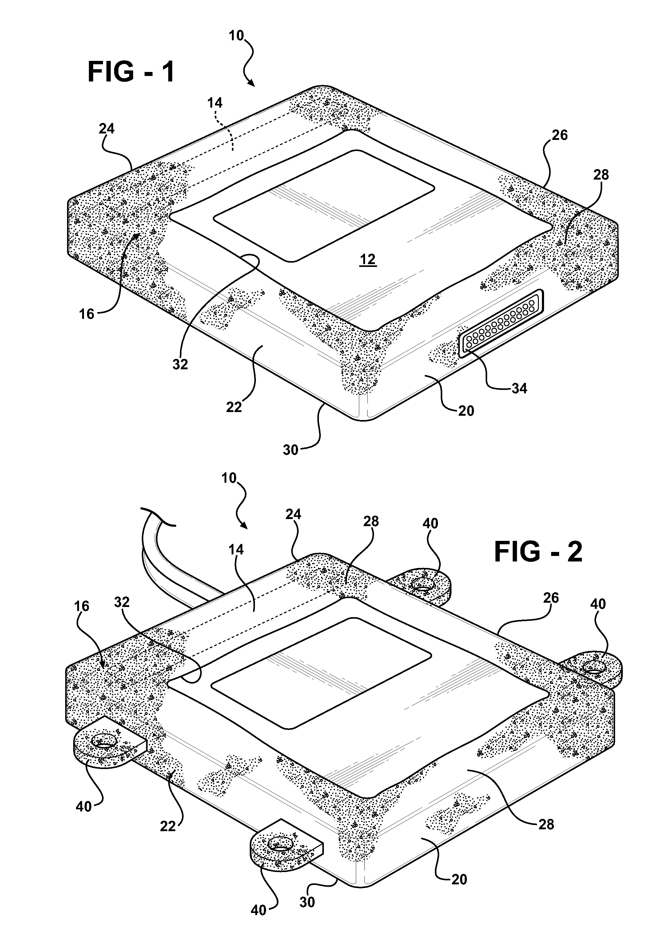
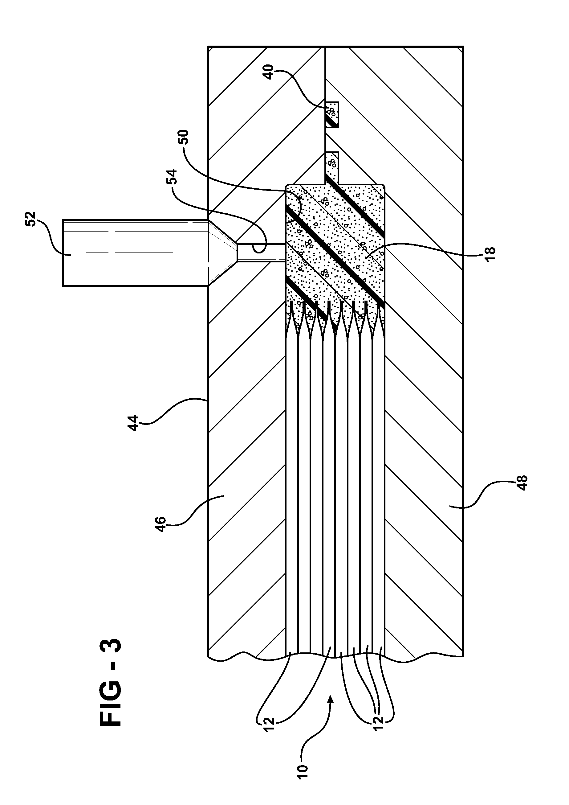
[0028]Referring to the Figures, wherein like numerals indicate like or corresponding parts, a battery pack or unit assembly (the assembly) of the present invention is generally shown at 10 in FIGS. 1 through 3. A first alternative embodiment of the present invention is generally shown at 100 in FIG. 4. A second alternative embodiment of the present invention is generally shown at 200 in FIGS. 5 and 6. The assemblies 10, 100, and 200 of the present invention are adaptable to be utilized in various configurations including and not limited to an overlapping battery cell packaging configuration and a vertical stack battery cell packaging configuration used in an automotive vehicle applications. Various cells are utilized with the present inventive concept. Preferably, lithium cells (the cells or cell) 12, 112, 212 are used with the present invention.

[0029]Alluding to the above, the assemblies 10, 100, and 200 of the present invention includes a lithium electronic controller (the LEC), s...


PUM

PropertyMeasurementUnit
Fractionaaaaaaaaaa
Timeaaaaaaaaaa
Densityaaaaaaaaaa

Abstract

A battery assembly has a plurality of battery packs each presenting a housing and multiple cells adjacent one and the other and disposed in the housing. A foam solution is injected into the case of each battery pack. The foam extends around each cell and the case to encapsulate each cell thereby eliminating air gaps between the cells and the case and receiving heat generating by the cells in operational mode of the battery pack.

Description

RELATED APPLICATIONS[0001]This non-provisional application claims priority to provisional application Ser. No. 60 / 797,539 filed on May 4, 2006 and 60 / 809,376 filed on May 30, 2006 and incorporated herewith by reference in its entirety.FIELD OF THE INVENTION[0002]The subject invention relates to battery packs having cells and more particularly, to a battery pack for electric / hybrid vehicles having a cooling system for cooling of the cells within the battery pack.BACKGROUND OF THE INVENTION[0003]Motor vehicles, such as, for example, hybrid vehicles use multiple propulsion systems to provide motive power. This most commonly refers to gasoline-electric hybrid vehicles, which use gasoline (petrol) to power internal-combustion engines (ICEs), and electric batteries to power electric motors. These hybrid vehicles recharge their batteries by capturing kinetic energy via regenerative braking. When cruising or idling, some of the output of the combustion engine is fed to a generator (merely t...

Claims


Application Information

Patent Timeline
08 Nov 2007
Publication
US20070259258A1
IPC
H01M10/50; H01M10/04; H01M50/209; H01M50/293
CPC
B29C44/1233; Y10T29/49108; F28D2021/0029; F28F9/005; H01M2/1077; H01M2/1094; H01M10/0481; H01M10/052
Inventors
BUCK, DERRICK SCOTT