Battery assembly and method of forming the same

a battery and assembly technology, applied in the field of rechargeable battery pack assembly, to achieve the effect of reducing weight, improving structural integrity of battery assembly, and efficient packaging characteristics

Active Publication Date: 2012-06-05
ENERDEL
View PDF8 Cites 7 Cited by
  • Summary
  • Abstract
  • Description
  • Claims
  • Application Information

AI Technical Summary

Benefits of technology

[0018]An advantage of the present invention is to provide a battery assembly presenting a self-locating mechanical connection that increases structural integrity of the battery assembly required while individual cells of the battery assembly are transported between various locations.
[0019]Another advantage of the present invention is to provide a battery assembly having efficient packaging characteristics.
[0020]Still another advantage of the present invention is to provide a battery assembly that reduces the weight by eliminating connecting hardware such as electrical studs and the like.
[0021]Still another advantage of the present invention is to provide a battery assembly that reduces manufacturing costs due to simplified assembly pattern.

Problems solved by technology

The United States Patent Publication Nos. 20050123828 to Oogami et al. and 20050271934 to Kiger et al. present several disadvantages such as failure to provide a battery assembly with self-locating mechanical elements aimed to increase structural integrity of the battery assembly required while individual cells of the battery assembly are transported between various locations and do not reduce the weight of the battery assembly.

Method used


Image

  • Battery assembly and method of forming the same
  • Battery assembly and method of forming the same
  • Battery assembly and method of forming the same

Examples


Embodiment Construction

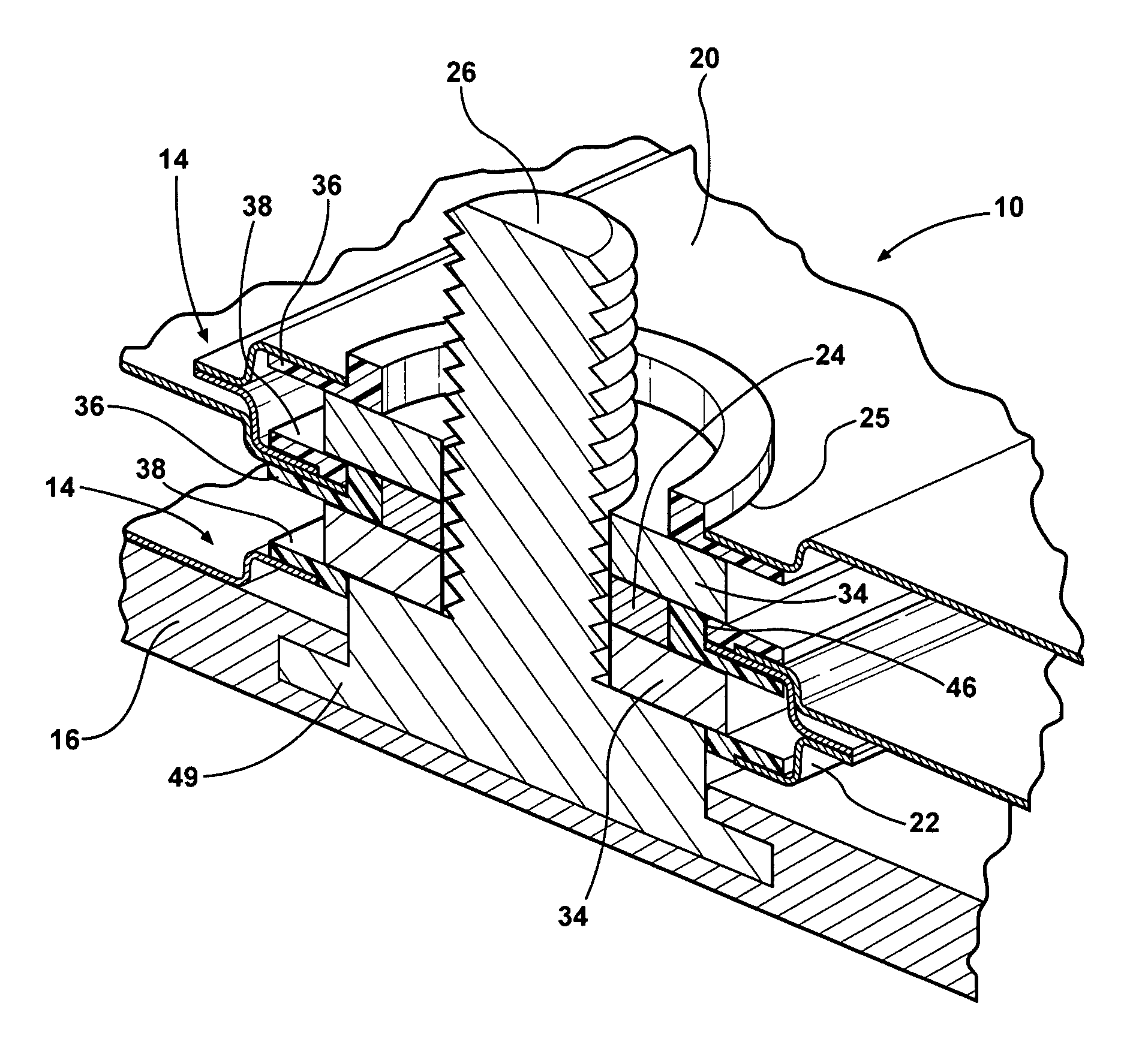
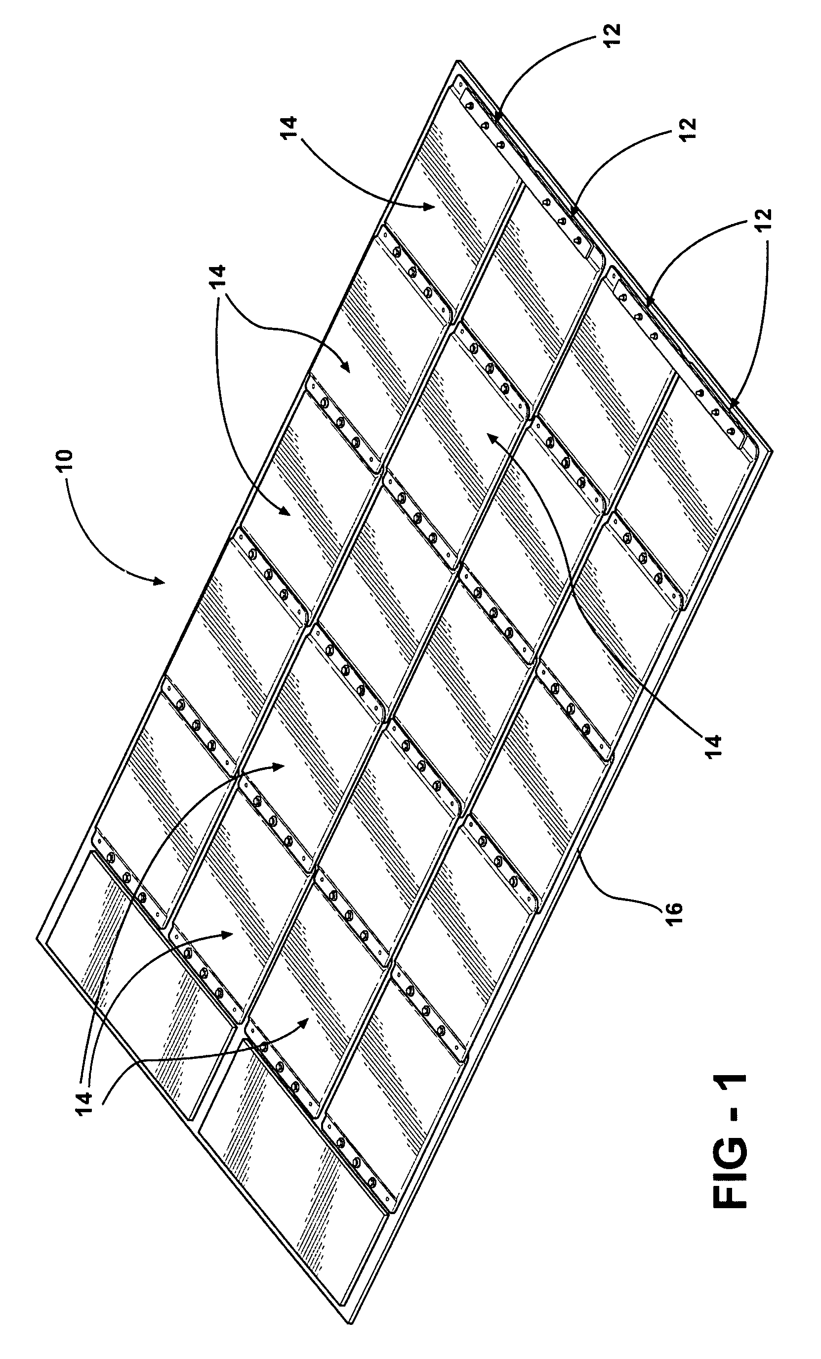
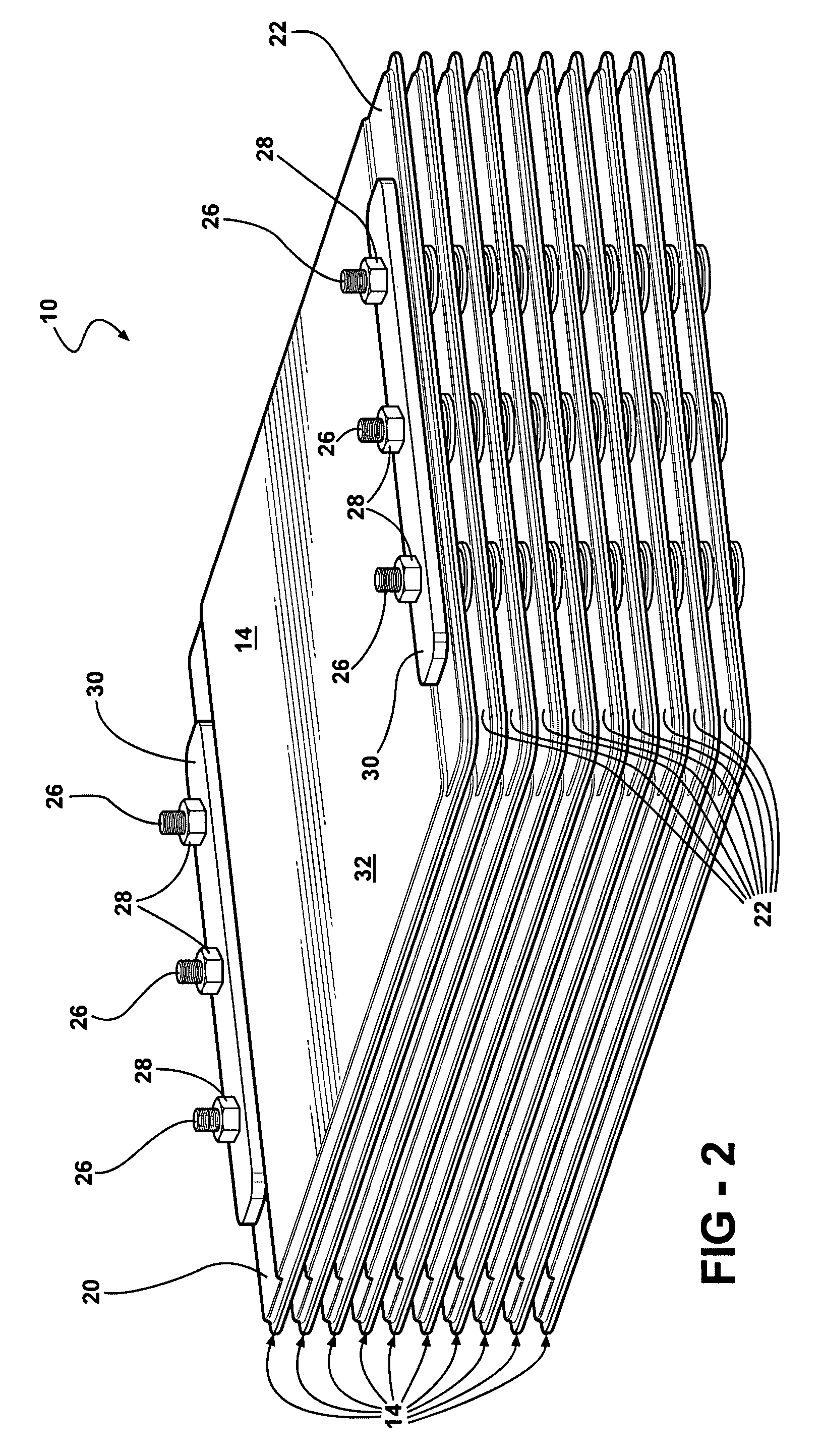
[0029]Referring to the Figures, wherein like numerals indicate like or corresponding parts, a battery assembly or a battery pack of the present invention is generally shown at 10. Preferably, the battery pack 10 includes four rows, generally indicated at 12, of battery cells (the cell), generally indicated at 14, connected with and extending along each row 12 in overlapping relationship. Each row 12 includes five stacks of the cells 14. Each stack of the cells 14 are interconnected with one another in the pattern known to those skilled in the battery art and extend along each row 12 in overlapping relationship with one another. The battery pack 10 is supported by and connected to a tray 16 formed from a polymeric material. A battery pack 10 of the present invention is adaptable to be utilized in various configurations including and not limited to an overlapping battery cell packaging configuration, as illustrated in FIGS. 1, 3, 4, and 6, a vertical stack battery cell packaging confi...


PUM

PropertyMeasurementUnit
insulatoraaaaaaaaaa
sizeaaaaaaaaaa
flexibleaaaaaaaaaa

Abstract

A battery assembly includes a first cell and a second cell adjacent the first cell. A first insulator and a second insulator extend over and encapsulate first electrode and second electrode. A shell extends over the first and second insulators thereby encapsulating the first and second insulators. A mechanical connection is defined between the first insulator of the fist cell and the second insulator of the second cell.

Description

RELATED APPLICATIONS[0001]This application claims priority to The U.S. Provisional Patent Application Ser. No. 60 / 727,779 filed Mar. 4, 2006, which is hereby incorporated by reference.FIELD OF THE INVENTION[0002]The subject invention relates to battery packs, and more particularly to rechargeable battery pack assembly having electrical and mechanical components arranged to reduce overall battery pack size and increase reliability and improve safety characteristics.BACKGROUND OF THE INVENTION[0003]Motor vehicles, such as, for example, hybrid vehicles use multiple propulsion systems to provide motive power. This most commonly refers to gasoline-electric hybrid vehicles, which use gasoline (petrol) to power internal-combustion engines (ICEs), and electric batteries to power electric motors. These hybrid vehicles recharge their batteries by capturing kinetic energy via regenerative braking. When cruising or idling, some of the output of the combustion engine is fed to a generator (merel...

Claims


Application Information

Patent Timeline
Patent Type & Authority Patents(United States)
IPC IPC(8): H01M2/14H01M2/00H01M50/211
CPCH01M2/1077H01M10/0481H01M10/0413Y02E60/10H01M50/211
Inventor KEMPER, PAUL LESLIEBUCK, DERRICK SCOTTSILK, BRUCE JAMES
Owner ENERDEL
Why Eureka
Try Eureka