Lighting strip

a technology of light-emitting modules and light-emitting tubes, which is applied in the direction of semiconductor devices for light sources, coupling device connections, lighting and heating apparatus, etc., can solve the problems of glass tube breaking, high failure rate, and high failure rate of neon type lamps used in signs. to achieve the effect of increasing structural integrity

Inactive Publication Date: 2006-10-05
RYAN PATRICK H JR
View PDF23 Cites 73 Cited by
  • Summary
  • Abstract
  • Description
  • Claims
  • Application Information

AI Technical Summary

Benefits of technology

[0015] The first heat-sink may, if desired, be formed from a first substantially rectangular member adjacently spaced to a second heat-sink formed as a second substantially rectangular member. Each of the rectangular members has a facing edge. The first rectangular member has one of its short sides connected about the insulated portion of the first electrical conducting wire. The first rectangular member has a resistor with one end electrical connected to the first rectangular member and the other end electrical connected to the first electrical conducting wire. The second rectangular member has a selective portion of one long side connected about the second electrical conducting wire. The first and second rectangular members have the light emitter connectively suspended therebetween. The second rectangular member is of a selected geometrical shape and has a sufficient thermal gradient to conduct the thermal energy away from the light emitter.
[0016] If desired, the first rectangular member's other short side may be connected about the selected insulated portion of the second electrical conducting wire. A selected portion of the other long side of the second rectangular member may be connected about a selected insulated portion of the first electrical conducting wire. Further, to increase the structural integrity of the present invention to the electrical conducting wires a selected portion of the second rectangular member's long side may be connected about a selected insulated portion of the first electrical conducting wire.

Problems solved by technology

The standard neon type lamps are known to have a high rate of failure when used in a sign application.
The high failure rate is attributed to the glass tube breaking due to sudden shocks or bumps experienced under normal manufacturing or shipping conditions.
Additionally, standard filament bulb type lamps are known to generate a large amount of heat during their operation.
The heat generated by standard filament bulb type lamps not only shortens the life of the light source but may cause thermal damage, deformation, cracking or the like to other nearby lighting elements, such as the deformation or cracking of a nearby plastic lens.
However, materials having low thermal conductivity necessarily have a correspondingly low electrical conductivity.
Therefore, the methods used in the art to minimize the thermal damage of the LED lamps during the soldering operation has resulted in the construction of a LED module that does not display optimal electrical efficiency.
Additionally, LED leads constructed from such low thermal conductivity materials effectively limit the amount of power that the LED can dissipate and remain within reliable operational parameters.
Mounting LED lamps on a printed circuit board is also costly.
The boards themselves are costly.

Method used


Image

  • Lighting strip
  • Lighting strip
  • Lighting strip

Examples


Embodiment Construction

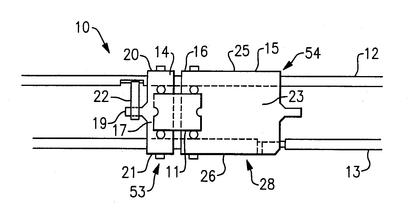
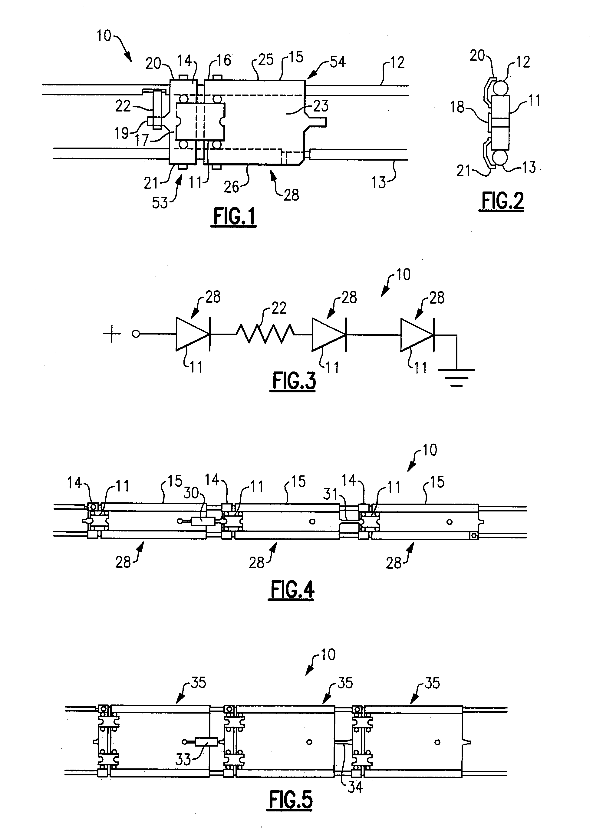
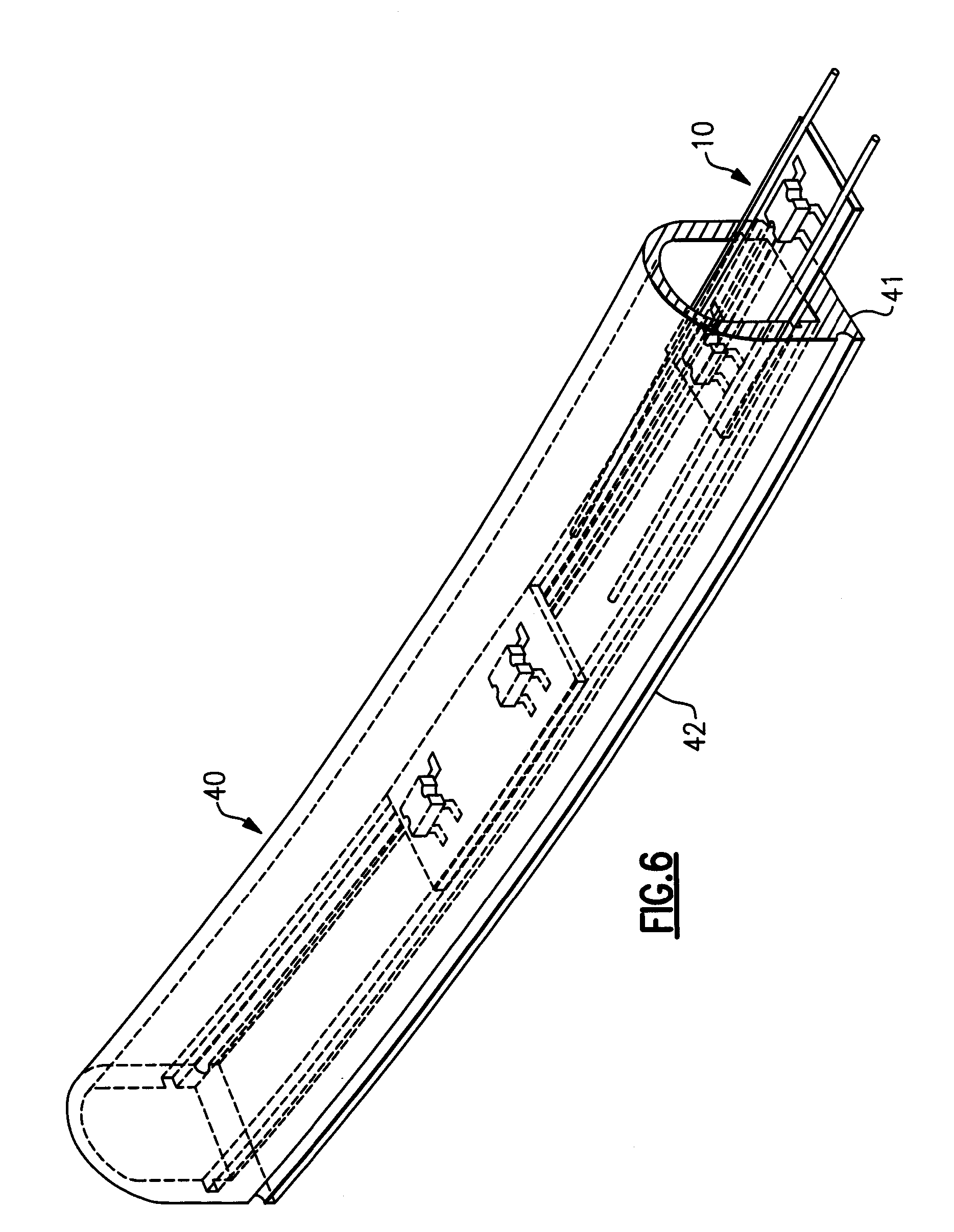
[0039] Before describing in detail the particular improved light-emitting module in accordance with the present invention, it should be observed that the present invention resides primarily, though not exclusively, in a novel structural combination of conventional materials and discrete components associated with the aforementioned light-emitting module and not in the particular detailed configuration thereof. Accordingly, the structure and arrangement of these conventional components have, for the most part, been illustrated in the drawings by readily understandable diagram representations and schematic diagrams. The drawings show only those specific details that are pertinent to the present invention in order not to obscure the disclosure with structural details which will be readily apparent to those skilled in the art having the benefit of the description herein. For example, a light emitter 1, FIG. 2 may, if desired, be any convenient light emitter connected to the present inve...


PUM


Abstract

The lighting strip has two elongated flexible conductors for carrying primary power to a plurality of modules. Each module has rectification diodes and a series lighting element. The series lighting element has at least one resistor and at least one light emitting diode (LED). The LED operates using the full-wave rectified power. The lighting strip may be provided in a spool which can be easily cut to the desired length. The number of light emitting diodes in a module, the spacing between components in a module, and the use of multiple lighting strips, can be selected to provide the desired illumination level or effect.

Description

PRIORITY CLAIM [0001] This is a continuation-in-part of U.S. patent application Ser. No. 11 / 304518, filed Dec. 14, 2005, which is a divisional of U.S. patent application Ser. No. 10 / 460072, filed Jun. 12, 2003, now U.S. Pat. No. 7,000,999.FIELD OF THE INVENTION [0002] The present invention relates, in general, to a light-emitting module. In particular, the present invention relates to a light-emitting module suspended between a pair of electrical conducting wires or electrically isolated conductors. More particularly, the invention relates to a plurality of light emitting modules ganged together to produce desired illumination. BACKGROUND OF THE INVENTION [0003] A light emitting diode (LED) is a type of semiconductor device that emits a visible light when biased in the forward direction. Lamps incorporating such LEDs as their light source are referred to as LED lamps. Due to their construction, LED lamps are typically smaller than standard neon type lamps, making their use particula...

Claims


Application Information

Patent Timeline
Patent Type & Authority Applications(United States)
IPC IPC(8): F21V1/00
CPCF21K9/00F21S4/003H05K1/189F21Y2101/02F21V17/007F21S4/20F21Y2115/10
Inventor RYAN, PATRICK H. JR.
Owner RYAN PATRICK H JR
Why Eureka
Try Eureka