Umbrella-type tent apparatus and method

Inactive Publication Date: 2001-05-15
OUTDOOR SPORTS PROD
View PDF8 Cites 74 Cited by
  • Summary
  • Abstract
  • Description
  • Claims
  • Application Information

AI Technical Summary

Problems solved by technology

The task of erecting this type of tent can be quite challenging since it involves maintaining the central tent pole in a vertical orientation while pulling the fabric outwardly and securing the periphery of the fabric with the tent pegs.
While umbrella-type tents have become rather ubiquitous, I have found a number of drawbacks to these types of tents.
Another problem is that when the umbrella-type tent is collapsed the fabric loops that engage the tent shell to the poles slide down the tent pole to a position that causes the loop to interfere with the smooth operation of the tent the next time the tent is erected.
If the fabric loop binds on the tent pole instead of smoothly sliding up the tent po

Method used


Image

  • Umbrella-type tent apparatus and method
  • Umbrella-type tent apparatus and method
  • Umbrella-type tent apparatus and method

Examples


Example

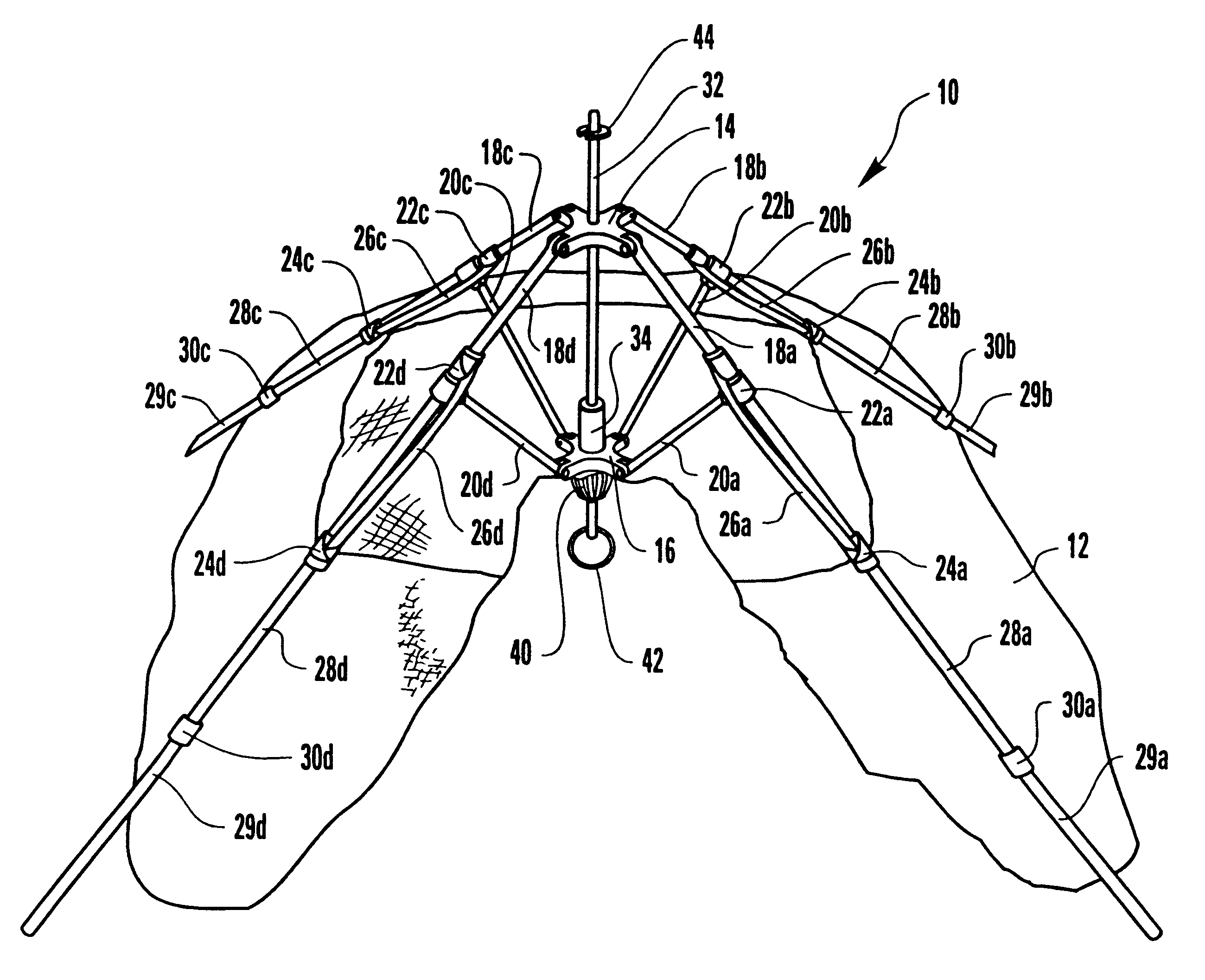
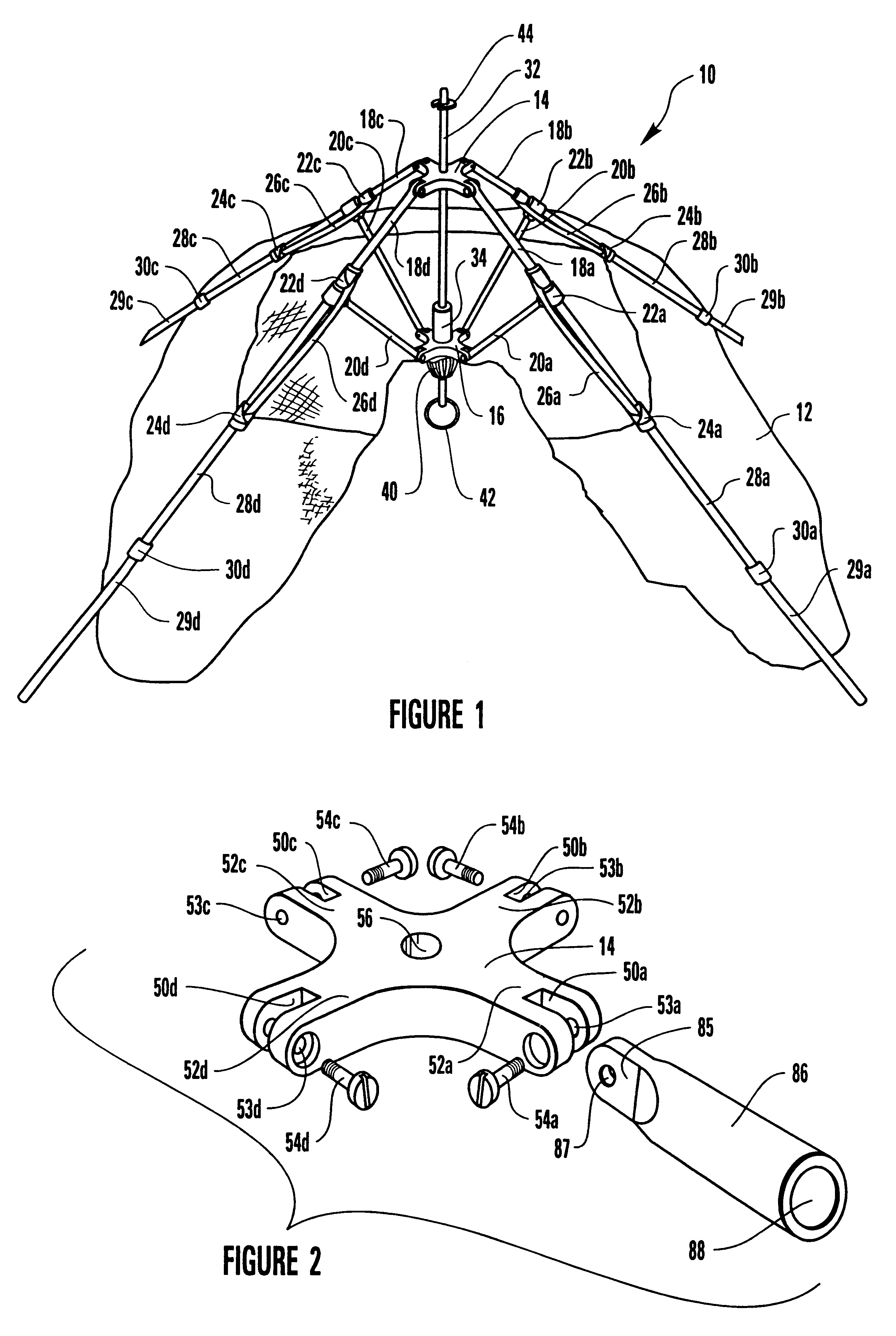
Referring now to FIG. 1, the improvements to the umbrella-type tent apparatus are shown generally at 10 as my novel support framework and are shown in the environment of a fabric tent shell 12, only a portion of which is shown herein for ease of presentation. Support framework 10 includes a top hub 14, a center hub 16, four tent poles 18a-18d hingedly engaged to the top hub 14, and four ribs 20a-20d hingedly engaged between tent poles 18a-18d and center hub 16. Four rib anchors 22a-22d are secured to tent poles 18a-18d, respectively, and serve as the hinged anchorage of the respective ribs 20a-20d to tent poles 18a-18d. Fabric tent shell 12 is slidingly mounted to tent poles 18a-18d by a plurality of fabric loops 24a-24d, respectively, only four of which are shown herein although other fabric loops (not shown) are positioned at spaced locations on fabric tent shell 12 along each of tent poles 18a-18d to provide the necessary connection between fabric tent shell 12 and tent poles 18a...


PUM


Abstract

A support framework for an umbrella-type tent, the tent including a fabric tent shell suspended from the support framework. The top and center hubs for the support framework are fabricated from a suitable material so as to provide increased strength to the top hub and the center hub. The fabric tent shell is tethered to the support framework to limit slippage of the fabric tent shell down the tent poles. The tent poles are segmented so as to provide foldable tent poles. A bungee cord keeper system is incorporated into the upper coupling for the segmented tent pole.

Description

1. Field of the InventionThis invention relates to umbrella-type tents and, more particularly, to an improved umbrella-type tent apparatus and method having a novel hub assembly system, a novel bungee cord retainer system for the poles, and a unique tether system for preventing the fabric of the tent shell from sliding too far down the pole as the umbrella-type tent is erected and / or collapsed.2. The Prior ArtTents have been well-known throughout history for use as a portable structure designed primarily to protect the inhabitants thereof from the elements. The simplest tent consisted of a flexible sheet of fabric or skins supported above the ground by a central tent pole with the periphery of the fabric held outwardly from the tent pole by a plurality of tent pegs. Such a structure is relatively simple to construct and to transport from place to place. The task of erecting this type of tent can be quite challenging since it involves maintaining the central tent pole in a vertical o...

Claims


Application Information

Patent Timeline
IPC IPC(8): E04H15/00E04H15/28E04H15/32
CPCE04H15/28E04H2015/326
Inventor REESE, FRANK P.
Owner OUTDOOR SPORTS PROD
Why Eureka
Try Eureka