

Plastic bag sealing device
- Summary
- Abstract
- Description
- Claims
- Application Information
AI Technical Summary
Benefits of technology
Problems solved by technology
Method used
Image

Examples
Embodiment Construction
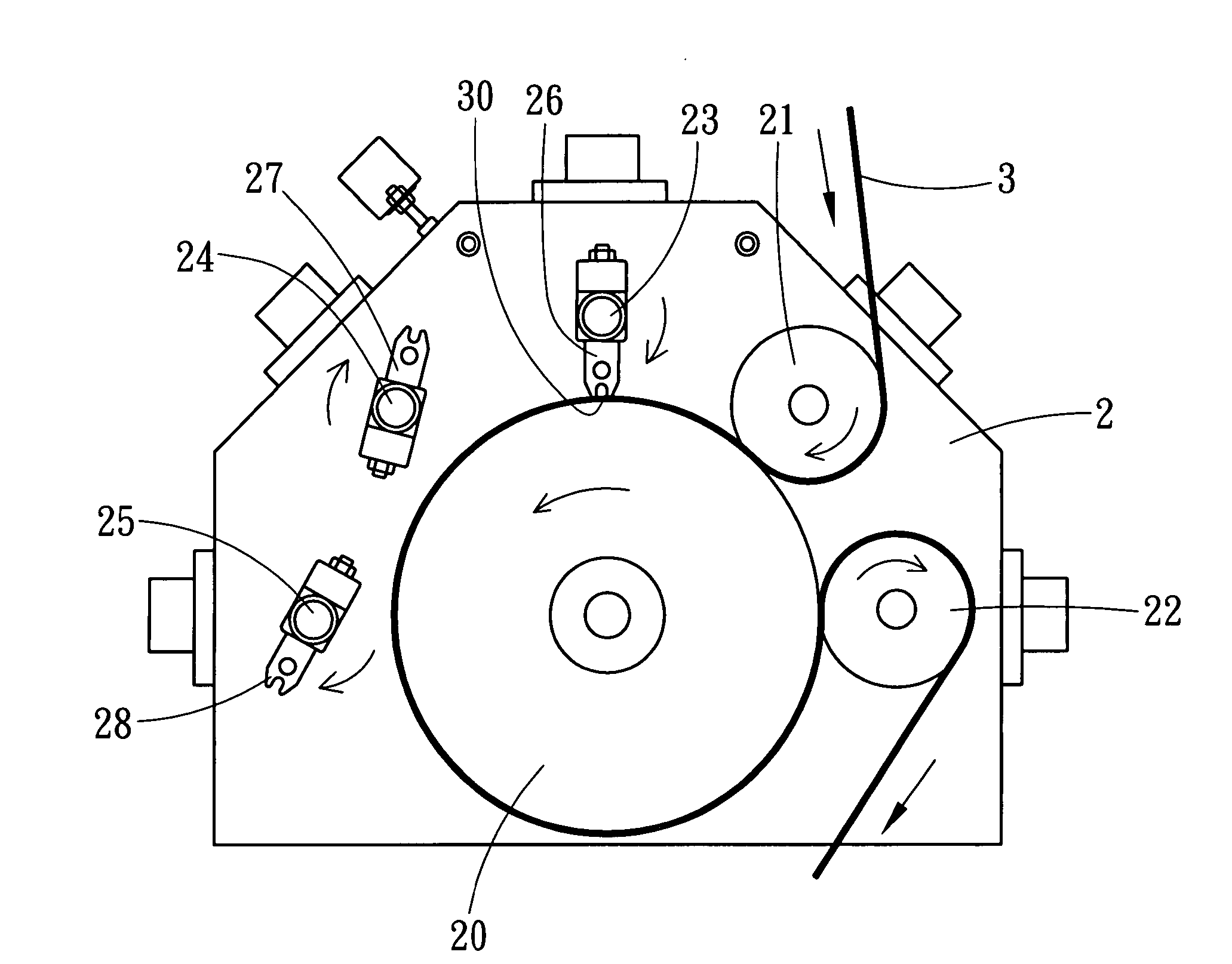
[0013] A preferred embodiment of a plastic bag sealing device in the present invention, as shown in FIG. 3, includes a work table 2, a silica gel roller 20 fixed on the work table 2, a material intake press roller 21 fixed on the work table 2 at one side of the silica gel roller 20, and a material outlet press roller 22 fixed on the work table 2 at one side of the silica gel roller and spaced apart from the material intake roller 21. The material intake roller 21 and the material outlet press roller 22 all press on the silica gel roller 20. Further, a first rotating shaft 23, a second rotating shaft 24 and a third rotating shaft 25 are all fixed on the work table, spaced apart around the other side of the silica gel roller 20, respectively fixed thereon with a first sealing blade 26, a second sealing blade 27, and a third rotating shaft 25. When the first, the second and the third sealing blade 26, 27 and 28 are rotated to contact with the silica gel roller 20 in due order, they wil...
PUM
 Abstract
Description
Claims
Application Information