Organic light emitting display device and power supply unit for the same

Inactive Publication Date: 2007-11-22
SAMSUNG DISPLAY CO LTD
View PDF12 Cites 6 Cited by
  • Summary
  • Abstract
  • Description
  • Claims
  • Application Information

AI Technical Summary

Benefits of technology

[0018]Aspects of the present invention respectively provide a dual-module organic l

Problems solved by technology

Accordingly, the manufacturing costs and the weight of th

Method used


Image

  • Organic light emitting display device and power supply unit for the same
  • Organic light emitting display device and power supply unit for the same
  • Organic light emitting display device and power supply unit for the same

Examples


Embodiment Construction

[0039]The present invention will now be described more fully with reference to the accompanying drawings, in which exemplary embodiments of the invention are shown. The invention may, however, be embodied in many different forms and should not be construed as being limited to the embodiments set forth herein; rather, these embodiments are provided so that this disclosure will be more thorough and complete, and will more fully convey the concept of the invention to those skilled in the art.

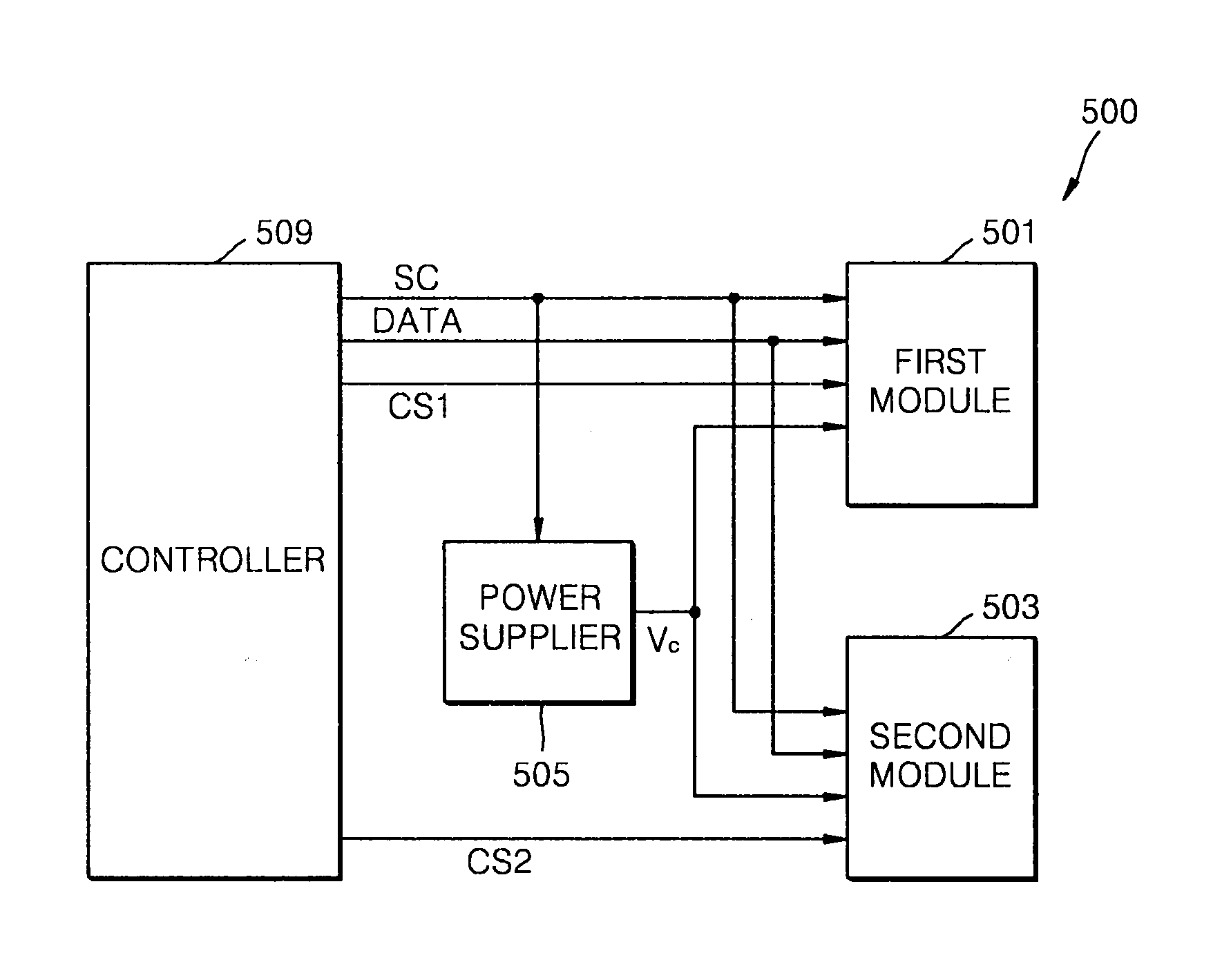
[0040]FIG. 5 is a block diagram illustrating an organic light emitting display device 500 according to an embodiment of the present invention.

[0041]Referring to FIG. 5, the organic light emitting display device 500 includes a first module 501, a second module 503, a power supplier (or power supply) 505, and a controller 509.

[0042]The first and second modules 501 and 503 each include an organic light emitting display panel 2, a data driving source 5, and a scan drive source 6, each of which was prev...


PUM


Abstract

An organic light emitting display device and a power supply for the same. In one embodiment, an organic light emitting display device includes a first module and a second module, each including an organic light emitting display panel and a driving source. A power supply is for supplying a first driving voltage to the first module and a second driving voltage to the second module. A controller is for applying a common control signal and a data signal to the first module and the second module and for applying a selection signal for selecting at least one of the first module or the second module.

Description

CROSS-REFERENCE TO RELATED PATENT APPLICATION[0001]This application claims priority to and the benefit of Korean Patent Application No. 10-2006-0043950, filed on May 16, 2006, in the Korean Intellectual Property Office, the entire content of which is incorporated herein by reference.BACKGROUND OF THE INVENTION[0002]1. Field of the Invention[0003]The present invention relates to an organic light emitting display device and a power supply for the same.[0004]2. Description of the Related Art[0005]Recently, self-emitting light display devices have received considerable attention. In particular, organic light emitting display devices have attracted much attention. The organic light emitting display devices include pixels corresponding to organic light emitting devices which emit light when an electric field is applied thereto.[0006]FIG. 1 is a schematic structural view of a conventional organic light emitting device 1. FIG. 2 is an equivalent circuit diagram of the conventional organic l...

Claims


Application Information

Patent Timeline
IPC IPC(8): G02B6/36
CPCG09G3/3208G09G2360/04G09G2330/028G09G2330/021G09G3/20G09G3/30G09G3/32
Inventor PARK, JUNG-KOOKKIM, SANG-WOOK
Owner SAMSUNG DISPLAY CO LTD
Why Eureka
Try Eureka