Surgical fixing device for two bone parts

a technology of surgical fixing and bone parts, which is applied in the direction of ligaments, surgical staples, prostheses, etc., can solve the problems of difficulty in the application of such a devi

Inactive Publication Date: 2007-11-22
AESCULAP AG
View PDF16 Cites 160 Cited by
  • Summary
  • Abstract
  • Description
  • Claims
  • Application Information

AI Technical Summary

Benefits of technology

[0039] It is advantageous if the engaging elements carry pointed fixing projections that point in the direction of the respective other engaging element, and by which they enter the substance of the bone and are thereby held on the bone parts.
[0040] The fixing projections may be inclined with respect to the tensioning device of the two engaging elements. In this case, it is advantageous if the fixing projections are inclined toward each other, that is to say if the spacings between the fixing projections at the engaging elements are greater than the spacings at the free ends of the fixing projections. This makes it easier for the bone parts to be pushed laterally in between the engaging elements.

Problems solved by technology

It is difficult for such a device to be applied, since on the one hand the two engaging elements must be positioned on the underside and on the upper side of the bone parts and since on the other hand the two bone parts also have to be appropriately brought together.
This can lead to problems in particular when engaging elements that have to be implanted in a specific direction are used, for example in the case of elongate, rectangular engaging elements.

Method used


Image

  • Surgical fixing device for two bone parts
  • Surgical fixing device for two bone parts
  • Surgical fixing device for two bone parts

Examples


Embodiment Construction

[0051] The ensuing detailed description provides exemplary embodiments only, and is not intended to limit the scope, applicability, or configuration of the invention. Rather, the ensuing detailed description of the exemplary embodiments will provide those skilled in the art with an enabling description for implementing an embodiment of the invention. It should be understood that various changes may be made in the function and arrangement of elements without departing from the spirit and scope of the invention as set forth in the appended claims.

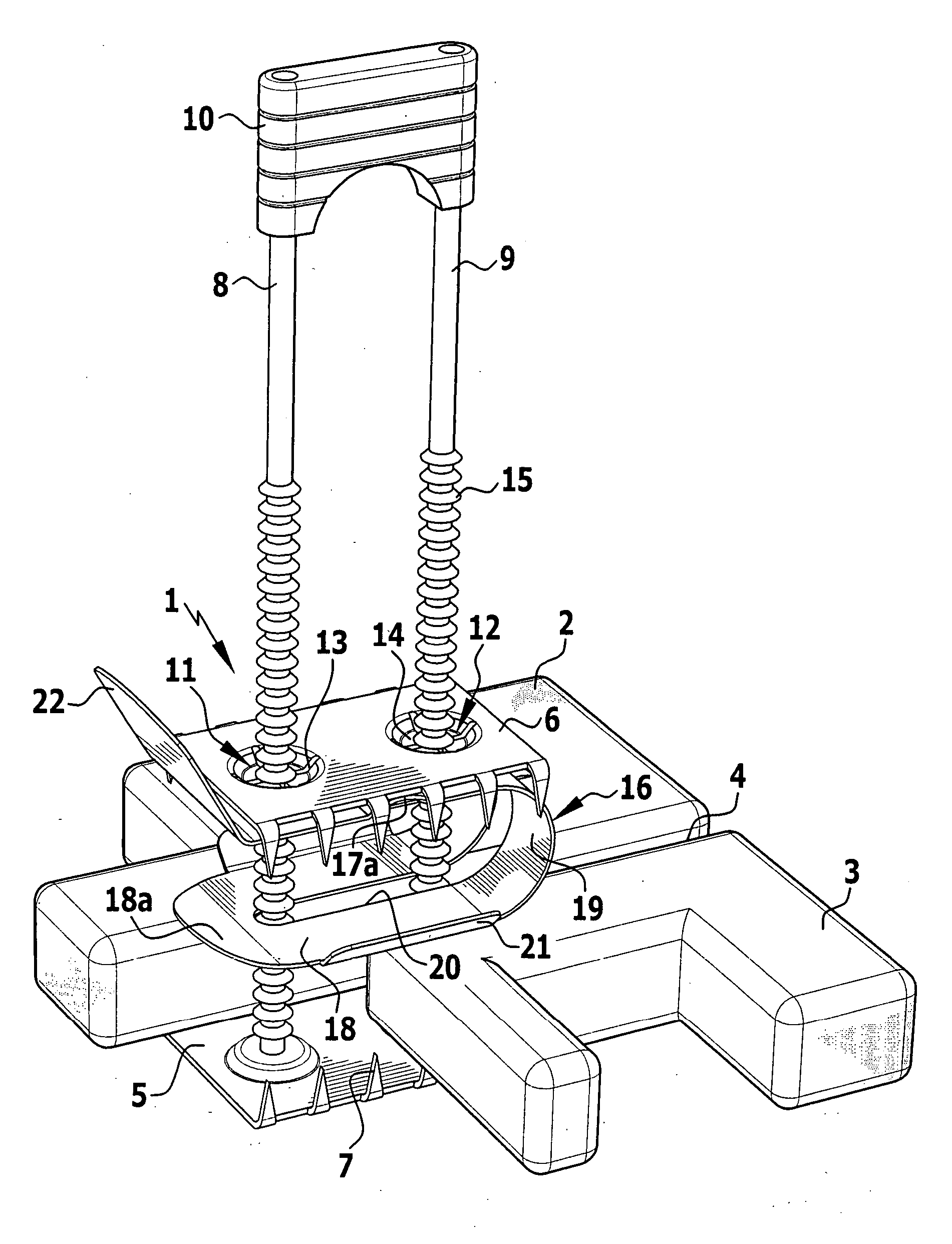
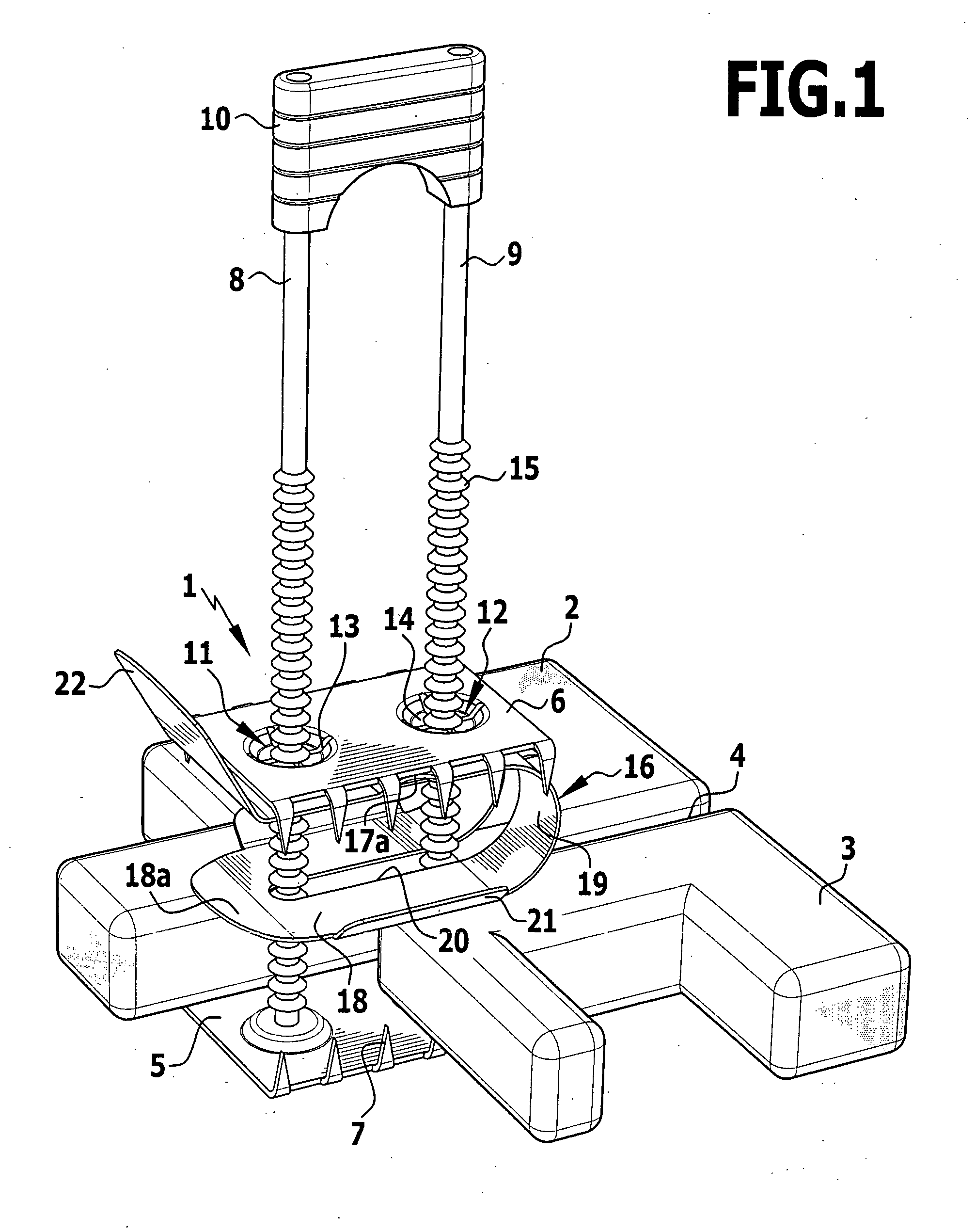
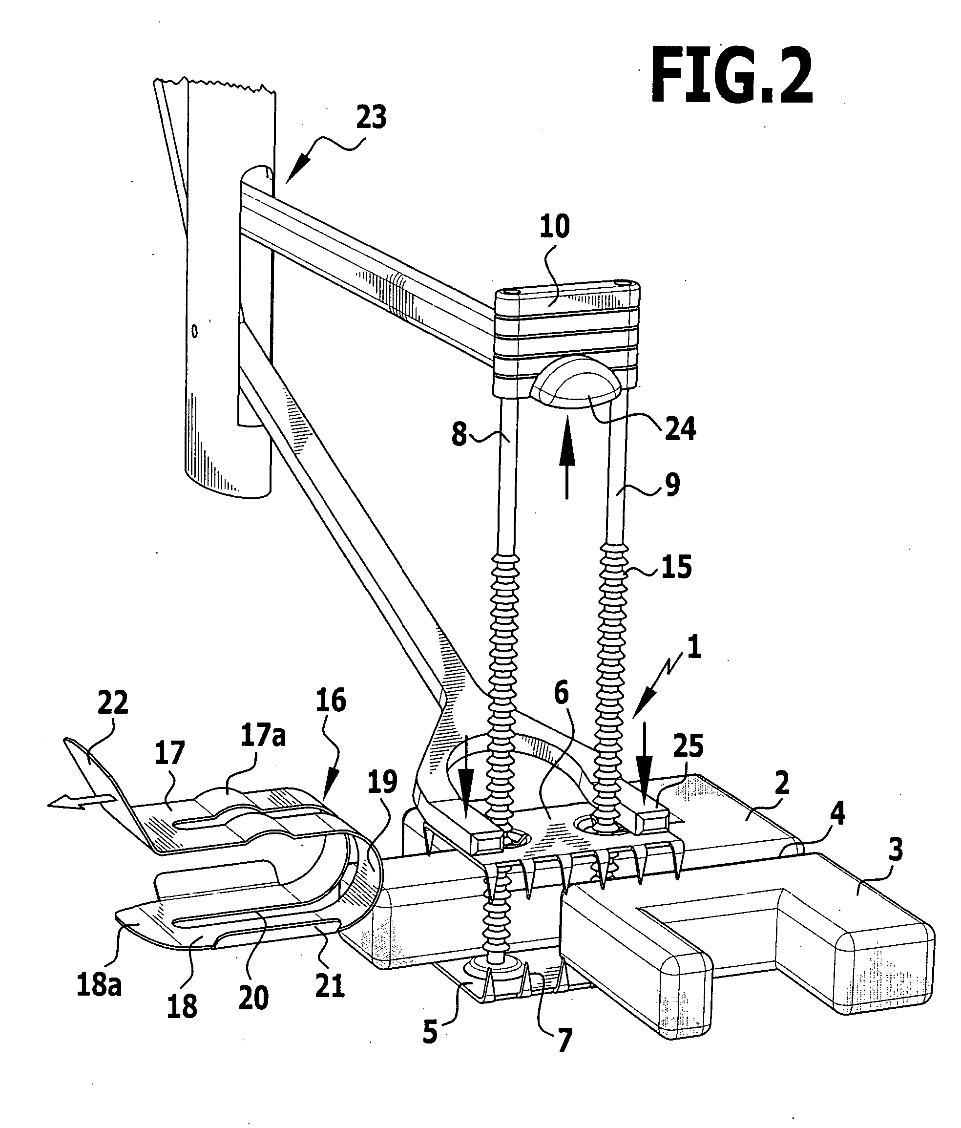
[0052] The fixing device 1 represented in the drawing serves for connecting two bone parts 2, 3 lying next to each other, which are only represented very schematically in the drawing. These may be two plate-shaped parts of the cranial bone, two parts of the sternum separated from each other by a saw cut or similar bone parts that are to be fixed in relation to each other while lying side by side, leaving a narrow interspace 4 between the two...


PUM


Abstract

A surgical fixing device for the fixing of adjacent bone parts is provided. A first engaging element is provided for engaging the underside of the two bone parts and a second engaging element is provided for engaging the upper side of the bone parts. A tensioning device connects the two engaging elements to each other through an interspace between the bone parts and permanently fixes the two engaging elements with respect to each other in a tensioned manner when they engage the underside and the upper side of the bone parts. To make it easier to apply the fixing device, at least one elastic tensioning element is provided which displaces a supporting surface applied to the upper side of the bone parts toward the first engaging element, so that the supporting surface and the first engaging element can be moved away from each other against the force of the elastic tensioning element.

Description

[0001] This application claims the benefit of German patent application no. 10 2006 021 025.5 filed on Apr. 28, 2006, which is incorporated herein and made a part hereof by reference. BACKGROUND OF THE INVENTION [0002] The invention relates to a surgical fixing device for the mutual fixing of two bone parts lying next to each other, having a first engaging element for engaging the underside of the two bone parts and having a second engaging element for engaging the upper side of the bone parts and having a tensioning device, which connects the two engaging elements to each other through an interspace between the bone parts and which permanently fixes the two engaging elements with respect to each other in a tensioned manner when they engage the underside and the upper side of the bone parts. [0003] Such a fixing device is known for example from DE 103 26 690 B4. With fixing devices of this type, two bone parts lying next to each other, for example two bone parts of the cranial bone ...

Claims


Application Information

Patent Timeline
Patent Type & Authority Applications(United States)
IPC IPC(8): A61B17/58
CPCA61B17/823A61B17/688
Inventor MORALES, PEDROWEISSHAUPT, DIETERDWORSCHAK, MANFREDLUTZE, THEODOR
Owner AESCULAP AG
Why Eureka
Try Eureka