Cage type jewelry links

a chain and chain technology, applied in the field of jewelry chains, can solve the problem that the width of arms cannot be uniform

Inactive Publication Date: 2007-12-06
ROZENVASSER AVRAHAM
View PDF2 Cites 14 Cited by
  • Summary
  • Abstract
  • Description
  • Claims
  • Application Information

AI Technical Summary

Benefits of technology

[0011] Furthermore, not only can there be at least two different colors and shapes along the width of the arm, but the actual elongation of the arm in the upward direction can differ with at least two different shapes. For example, one shape can be vertical upwardly from the base where the arms are interconnected, while at least one other arm may be arcuately extending upwardly from the base. It should be appreciated that the cage can have more than three arms, and again, so long as there are at least two different arms within the cage, such is contemplated in this invention.
[0012] Furthermore, once these cages are formed, they can be interconnected either manually or by a machine process. When connecting them either by hand or by machine, depending upon how the individual cages are interconnected one to the other and the angular relationship of one cage to the next cage and all of its previous cages, there can result an elongated chain with an entirely different effect. Chains having spiral colors or shapes that can be formulated in this manner, as well as chains having undulating patterns along the elongated length.

Problems solved by technology

Furthermore, the widths of the arms need not be uniform.

Method used


Image

  • Cage type jewelry links
  • Cage type jewelry links
  • Cage type jewelry links

Examples


Embodiment Construction

[0025] While this invention is illustrated and described in a preferred embodiment, the device may be produced in many different configurations, forms and materials. There is depicted in the drawings, and will herein be described in detail, preferred embodiments of the invention, with the understanding that the present disclosure is to be considered as an exemplification of the principles of the invention and the associated functional specification for its construction and is not intended to limit the invention to the embodiment illustrated. Those skilled in the art will envision many other possible variations within the scope of the present invention.

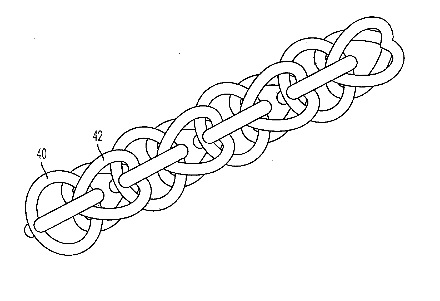
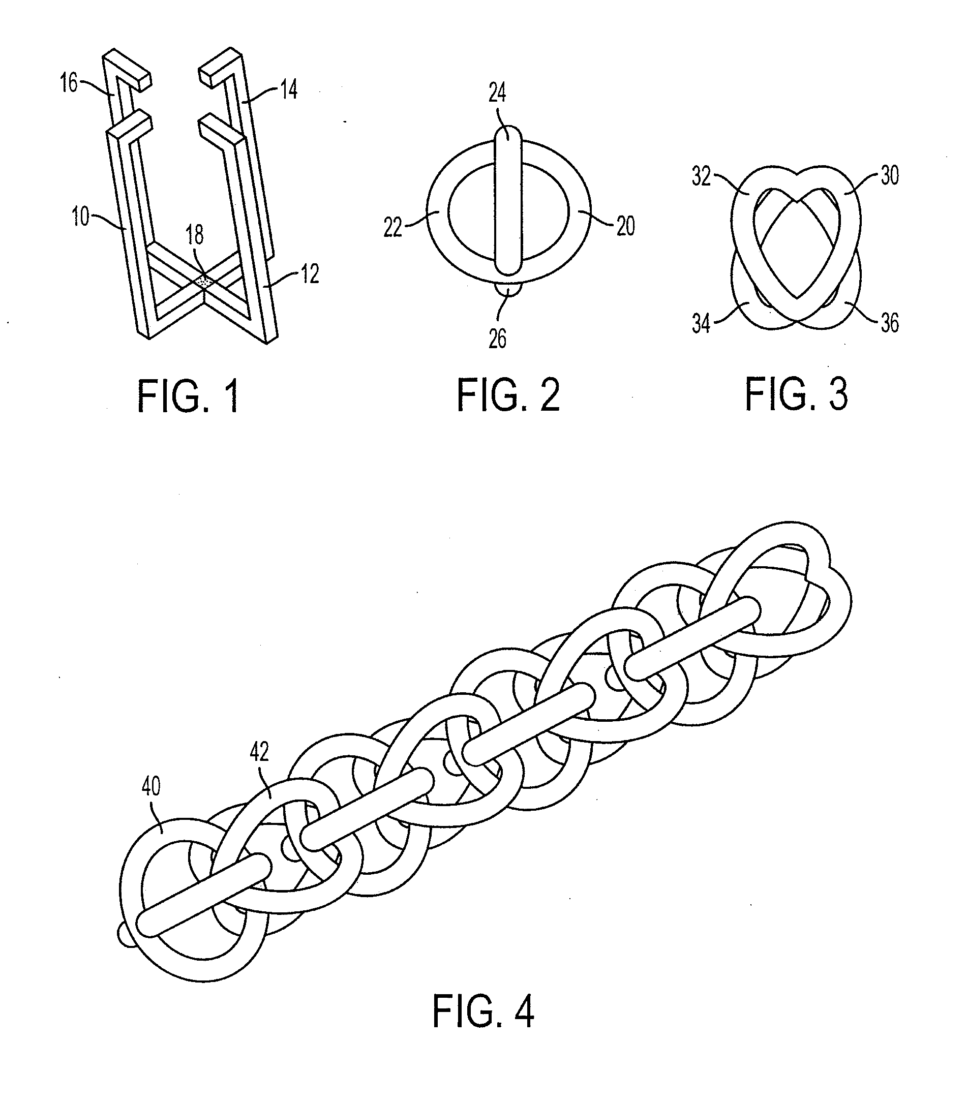
[0026] The present invention contemplates the use of individual cage elements in the formation of a chain. A cage element is defined as an element having more than two arms with the arms interconnected at a base portion and the arms extending upwardly from the base portion. By way of example, FIG. 1 shows a cage having four arms, 10, ...


PUM


Abstract

A chain including a plurality of cages connected together, each cage including at least two arms having at least one feature which distinguishes one or more of the at least two arms from a remainder of the arms, said at least arms being bent in a direction away from a base point.

Description

BACKGROUND OF THE INVENTION [0001] 1. Field of the Invention [0002] The present invention relates to articles of jewelry and specifically jewelry chains. [0003] 2. Discussion of Prior Art [0004] Jewelry chains are often made up of individual elements that are interconnected to form a chain whose length is then cut and clasps put at the end to form bracelets, necklaces, and the like. Also, such chain portions can be used as elements of other types of jewelry. [0005] In certain types of jewelry, individual links are utilized as the individual building blocks of the jewelry and such links are interconnected together. By way of example, the well known rope chain is made up of individual links and these links are woven or interconnected together to form the well known rope chain. Such links are typically a ring or loop of material that lies in a single plane with a gap located within the periphery. The links can be circular, rectangular, triangular or of any other shape but significantly...

Claims


Application Information

Patent Timeline
Patent Type & Authority Applications(United States)
IPC IPC(8): B21L11/00
CPCB21L11/005A44C11/00
Inventor ROZENVASSER, DAVID
Owner ROZENVASSER AVRAHAM
Why Eureka
Try Eureka