Adjustable and replaceable lens structure for portable electronic devices

a technology of electronic devices and lens structures, applied in the direction of mountings, optics, instruments, etc., can solve the problems of damage to electronic functions, misalignment of optical axes, and inability to adapt to universal appearance of external lens modules

Inactive Publication Date: 2014-07-10
DIGILENS
View PDF2 Cites 6 Cited by
  • Summary
  • Abstract
  • Description
  • Claims
  • Application Information

AI Technical Summary

Benefits of technology

[0010]The movable lens module is mounted on the lens-mounting body, and has a movable mechanism, a lens and an operation part. The movable mechanism is mounted on the lens-mounting body and is adapted to be mounted on the housing of the electronic device. The lens is connected with the movable mechanism. The connection part is connected with the movable mechanism. The movable mechanism can be operated to move along a straight line, rotate or pivot, thereby moving the lens to align with an optical axis of the movable lens module and varying the focus of field of view of the movable lens module. Accordingly, the lens with different picture-taking effect can be provided, such as a wide-angle, microscopic or telescopic lens.

Problems solved by technology

However, those external lens modules are not designed with universal appearance suitable for various models of portable electronic devices made by different manufacturers.
Some structures of those external lens modules are even incorrectly designed to cause damage to electronic function and optical axis misalignment.
Moreover, instead of serving as a wide-angle lens with good quality in taking wide-angle pictures and as a high power microscope lens for truly magnifying intricate details of objects taken in close-up pictures, those external lens modules are confined to serve as short-distance telephoto lens or low power microscopic lens only.

Method used


Image

  • Adjustable and replaceable lens structure for portable electronic devices
  • Adjustable and replaceable lens structure for portable electronic devices
  • Adjustable and replaceable lens structure for portable electronic devices

Examples


first embodiment

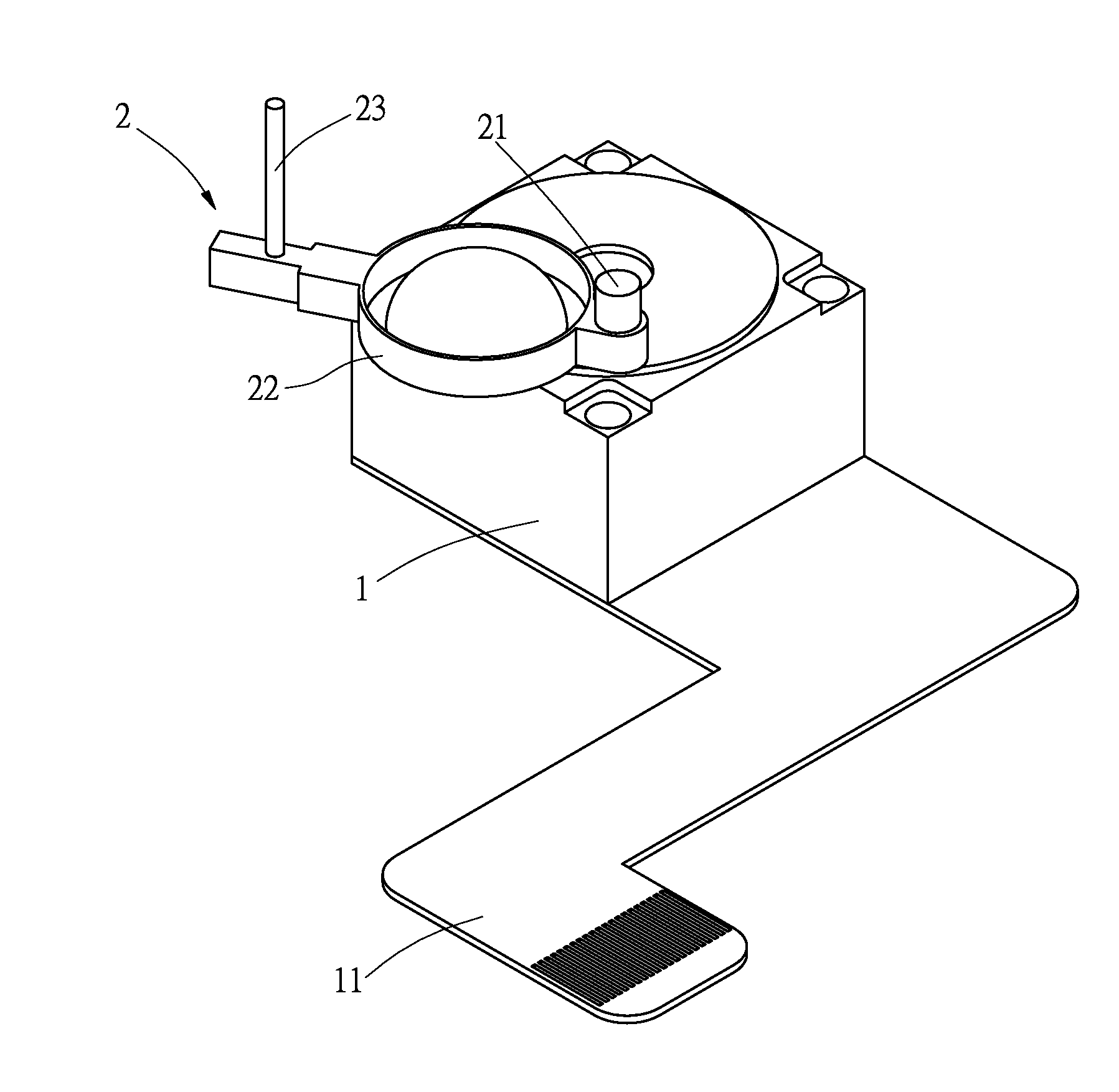
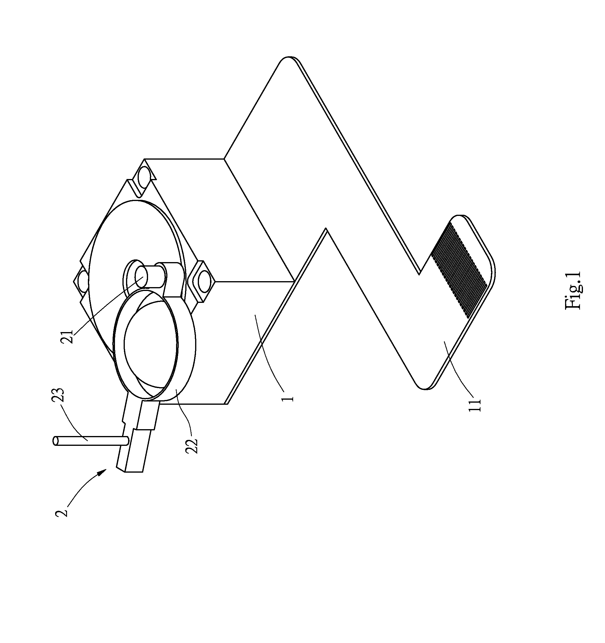
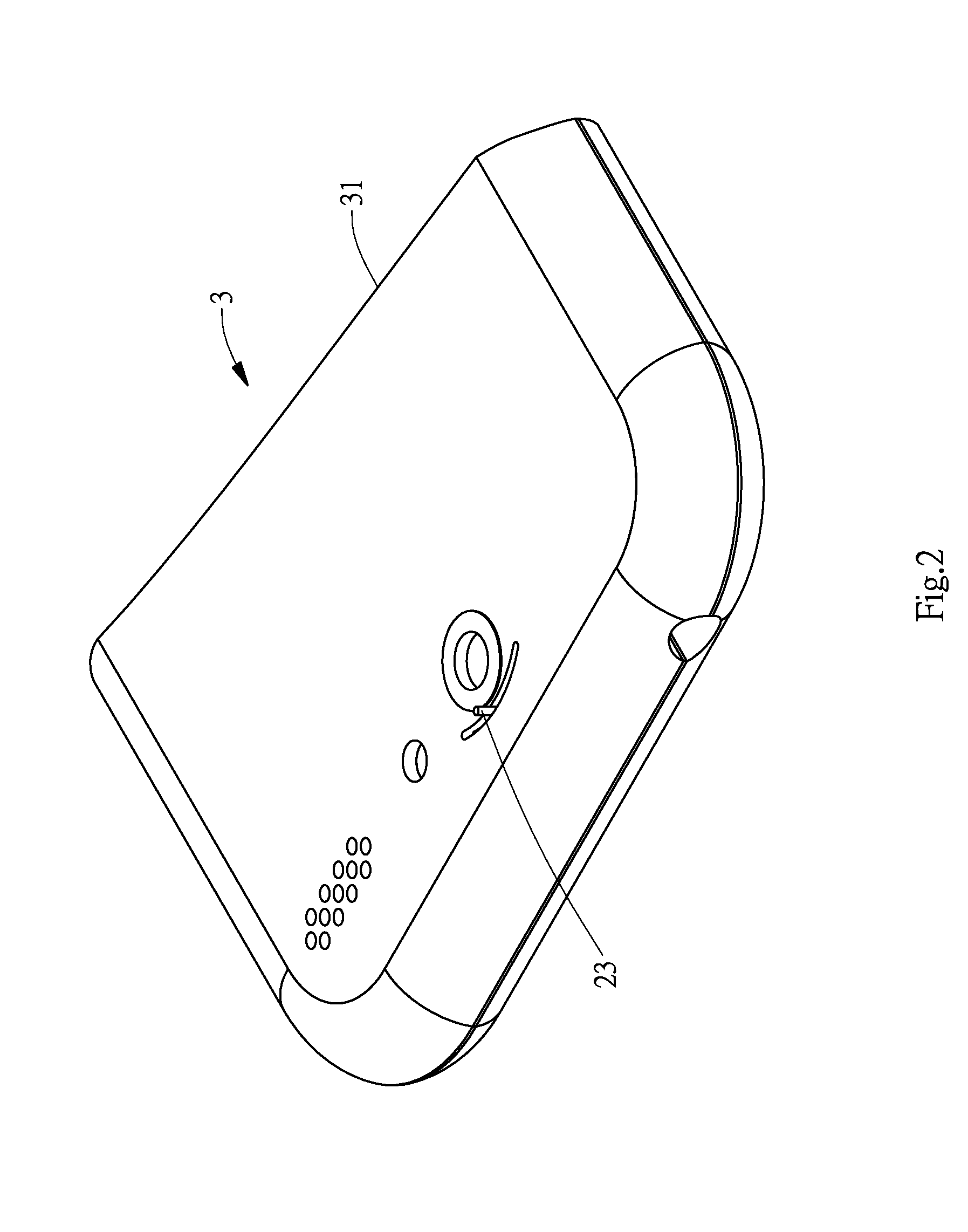
[0027]With reference to FIGS. 1 and 2, a movable and replaceable lens structure for portable electronic devices in accordance with the present invention has a lens-mounting body 1 and a movable lens module 2. The lens-mounting body 1 has a ribbon cable 11 connected therewith, and is electrically connected with an electronic device 3 through the ribbon cable 11. The movable lens module 2 is pivotally mounted on the lens-mounting body 1, and has a movable mechanism 21, a lens 22 and an operation part 23. The movable mechanism is mounted on the lens-mounting body 1. In the present embodiment, the movable mechanism 21 is a rotary shaft, and is pivotally mounted on one side of the lens-mounting body 1. The lens 22 is connected with the movable mechanism 21, and may be a wide-angle lens or a microscope lens with good quality. The operation part 23 is formed on and protrudes from the movable mechanism 21, and is pivoted with respect to a pivoting center at the rotary shaft for the lens 22 ...

third embodiment

[0031]With reference to FIG. 6, a movable and replaceable lens structure for portable electronic devices in accordance with the present invention has a lens-mounting body 1 and a movable lens module 2. The lens-mounting body 1 is mounted on and electrically connected to the electronic device 3. The movable lens module 2 is pivotally mounted on the lens-mounting body 1, and has a movable mechanism 21, a lens 22, and an operation part 23. The movable mechanism 21 is pivotally mounted on one side of the lens-mounting body 1. The lens 22 is mounted on the movable mechanism 21. Specifically, the operation part 23 and the movable mechanism 21 are concentric to each other, and the operation part 23 takes the form of a knob, protrudes beyond the electronic device 3, and is turned for operation. When the operation part 23 is turned, the lens 22 is driven and rotated with an optical axis thereof aligning with the optical axis of the movable lens module 2, thereby achieving another objective o...

seventh embodiment

[0036]With reference to FIG. 14, a movable and replaceable lens structure for portable electronic devices in accordance with the present invention is shown. In the present embodiment, the movable lens module 2 has a base 26, a track 25, a lens 22, a movable mechanism 21, and an actuation member 24. The base 26 is mounted on an inner side of the housing 31 of the electronic device 3, and is located atop of a lens of the electronic device 3. The track 25 is formed in the base 26. The lens 22 is movably mounted in the track 25, and has an arc-shaped or straight-line channel 221 formed in an end portion of the lens 22. The movable mechanism 21 is rod-shaped and is inserted in the channel 221 with one end of the movable mechanism 21 mounted in the lens 22 and the other end protruding beyond the channel 221. The actuation member 24 is connected with the end protruding beyond the channel 221. The lens is moved by moving the actuation member 24 to adjust the focus and the field of view of t...


PUM


Abstract

A movable and replaceable lens structure for electronic devices has a lens-mounting body mounted on and electrically connected with a electronic device, and a movable lens module mounted on the lens-mounting body and having a movable mechanism mounted on the lens-mounting body or a housing of the electronic device. The movable lens module has a movable mechanism mounted on the lens-mounting body or the housing of the electronic device. A lens is connected with the movable mechanism. An operation part is connected with the movable mechanism. The movable mechanism can be operated to move along a straight line, rotate or pivot, thereby moving the lens to align with an optical axis of the movable lens module and varying the focus of field of view of the movable lens module. Accordingly, the lens with different picture-taking effect can be provided, such as a wide-angle, microscopic or telescopic lens.

Description

BACKGROUND OF THE INVENTION[0001]1. Field of the Invention[0002]The present invention is related to an adjustable and replaceable lens for portable electronic devices, and more particularly to a lens structure mounted on a body or housing of a lens module with a lens being movably replaced and replaced according to a desired picture-taking effect.[0003]2. Description of the Related Art[0004]New generation portable electronic devices, such as smart phones and tablet computers, which possess processors with high computing power, and play an important role as an indispensable communication tool for daily life of modern people.[0005]Those advanced smart phones or tablet computers are basically equipped with simple fixed-focus lenses only due to the concern of appearance, size and weight, and generate short-distance or long-distance pictures in collaboration with built-in image processing technique upon taking pictures. In reality, those fixed-focus lenses can be at most positioned at th...

Claims


Application Information

Patent Timeline
Patent Type & Authority Applications(United States)
IPC IPC(8): G02B7/04
CPCG02B7/04G02B7/16G02B15/10G02B7/14
Inventor WU, CHEN-FENG
Owner DIGILENS
Why Eureka
Try Eureka