Wind-powered pneumatic engine and a motor vehicle equipped with the engine

a pneumatic engine and motor vehicle technology, applied in the direction of wind energy generation, parallel perpendicular air flow wind motor, etc., can solve the problems of only passively receiving limited wind force of engines, polluting the environment, etc., to save large hpca usage, the effect of enhancing the utilization rate and reducing the time of air jets

Inactive Publication Date: 2007-12-13
CONG YANG
View PDF5 Cites 48 Cited by
  • Summary
  • Abstract
  • Description
  • Claims
  • Application Information

AI Technical Summary

Benefits of technology

[0030] 4. Through the deceleration and brake pressurizing device and the second HPCA compressor, the kinetic energy produced as the motor vehicle decelerates and brakes is transmitted to the second HPCA compressor, and the second HPCA compressor subsequently recycles the braking energy and uses the braking energy to regenerate HPCA to be input into and stored in the air tank, such that the utilization of the energy is further enhanced. This solution is particularly suitable for the motor vehicle that frequently decelerates, brakes, and stops.
[0031] 5. Through the automatic intermittent burst and jetted HPCA, the air jet time is

Problems solved by technology

Engines using fuels as an energy source consume a large quantity of fuels, and discharge large amounts of waste gases and hot gases, which pollute the environment.
Since the mechanical devices installed with the eng

Method used


Image

  • Wind-powered pneumatic engine and a motor vehicle equipped with the engine
  • Wind-powered pneumatic engine and a motor vehicle equipped with the engine
  • Wind-powered pneumatic engine and a motor vehicle equipped with the engine

Examples


Embodiment Construction

[0045] The present invention is further described in detail with accompanying drawings and embodiments.

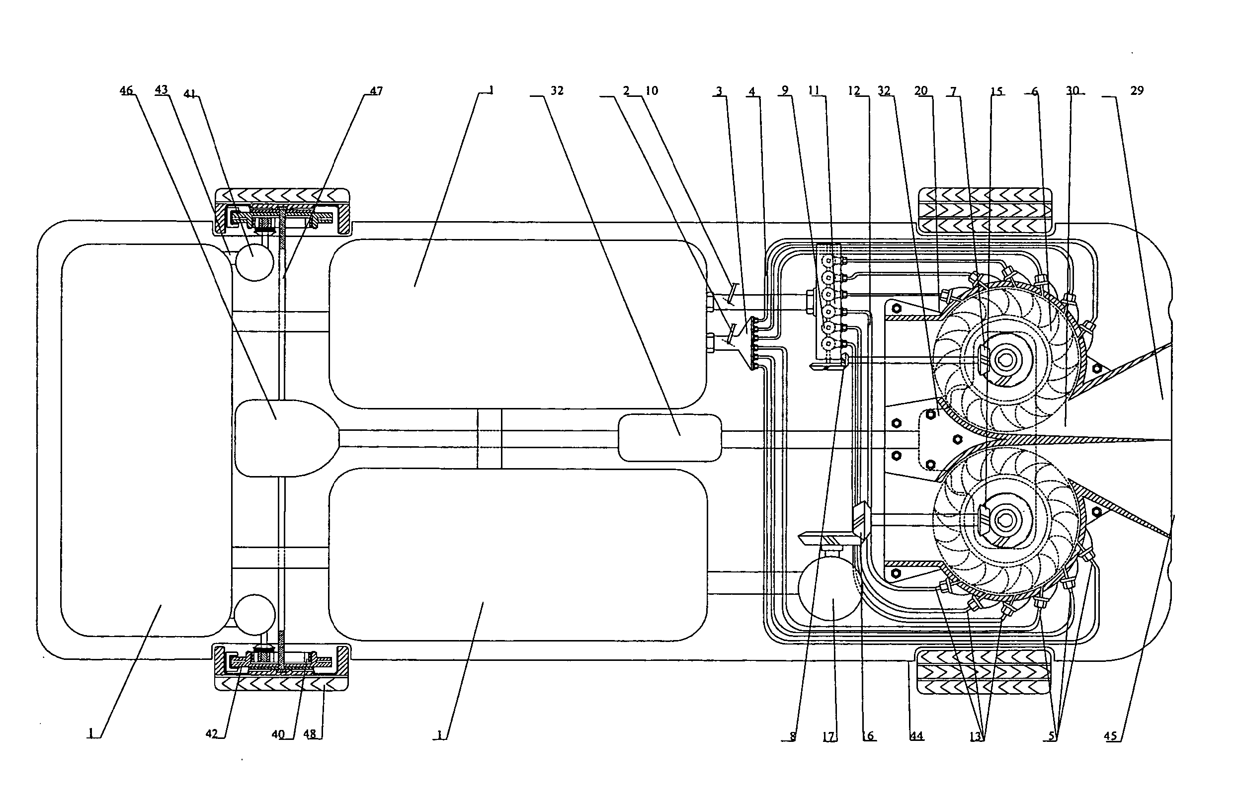
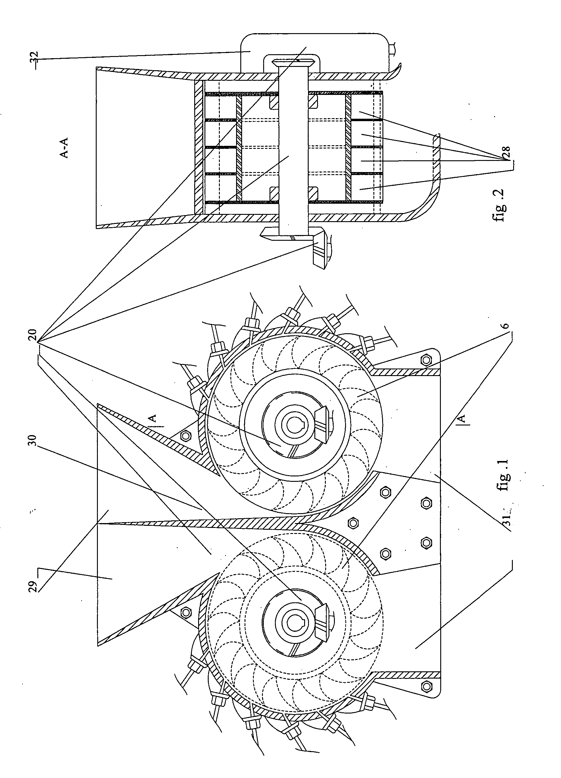
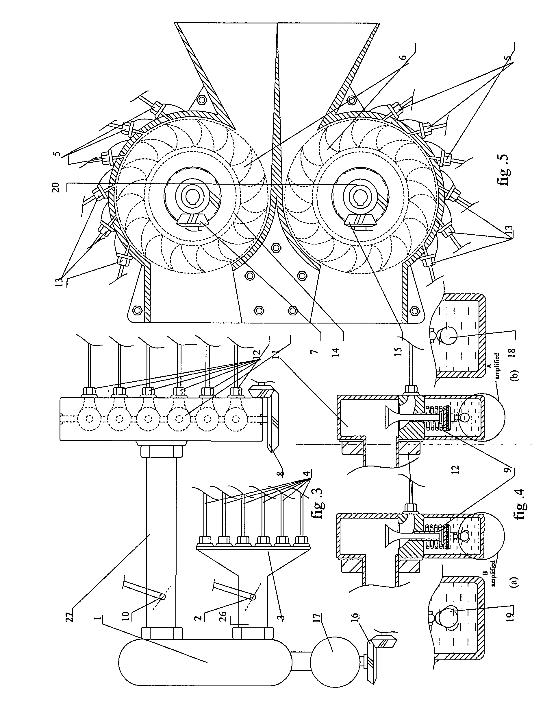
[0046] As shown in FIGS. 1-8, a wind-powered pneumatic engine 20 includes trunk shape inlets, each having an outer edge 29 and an inner edge 30, impeller chambers 28, impellers 6, impeller flywheels 14, a left impeller main shaft auxiliary power conical gear 7, a right impeller main shaft auxiliary power conical gear 15, a primary power output gear box 32, and air outlets 31; a HPCA regeneration, storage and supply system, including an air tank 1, a first HPCA compressor 17, and a conical gear 16 for transmitting the first HPCA compressor 17; an air-jet system for start and acceleration, including a first controller 2 for opening the HPCA to perform start and acceleration, a distributor 3, a first air-jet pipe set 4 connected with the distributor 3, a first air-jet nozzle set 5, a second controller 10 for opening the HPCA to perform automatic intermittent burst air-jet acceleratio...


PUM


Abstract

A wind-powered pneumatic engine including one or more impeller chambers and one or more impellers disposed in the impeller chambers is provided. One or more air inlets for receiving external wind resistance airflow are disposed on the impeller chambers, and the external wind resistance airflow entering the air inlets drives the impellers to operate to generate power output. The wind-powered pneumatic engine further includes an air-jet system for jetting HPCA into the impeller chambers, and the internal high-pressure compressed air jetted by the air-jet system in conjunction with the external wind resistance airflow entering the air inlets drives the impellers to operate to generate power output. In the present invention, the external resistance airflow around a motor vehicle moving at a speed is converted into power for use, which greatly reduces energy consumption and improves the moving speed of a motor vehicle. A motor vehicle equipped with wind-powered pneumatic engine is also provided.

Description

CROSS-REFERENCE TO RELATED APPLICATIONS [0001] This patent application is a continuation application of application PCT / CN2005 / 001911 filed Nov. 14, 2005 and published in Chinese, and claims the benefit of Chinese Patent Application No. 200410091154.2 filed Nov. 22, 2004, Chinese Patent Application No. 200510090760.7 filed Aug. 16, 2005, and Chinese Patent Application No. 200510117451.4 filed Nov. 2, 2005. BACKGROUND OF THE INVENTION [0002] 1. Field of the Invention [0003] The present invention relates to an engine installed in large, medium or small size cargo or passenger vehicles having steering wheels, railway trains, subway trains, marine travel vehicles, aerospace travel vehicles and all other motor vehicles that move at a certain speed, and relates to the field of machines. [0004] 2. Description of Related Art [0005] Engines using fuels as an energy source consume a large quantity of fuels, and discharge large amounts of waste gases and hot gases, which pollute the environmen...

Claims


Application Information

Patent Timeline
IPC IPC(8): B60K16/00F03D3/02F03B1/00F03D3/00F03D3/04F03D7/06F03D9/00F03D9/17
CPCB60K16/00B60K2016/006F03D3/005F03D3/02F03D9/028F05B2240/215B60L2200/26Y02E10/74Y02E60/15Y02T10/90B60L8/006Y02E70/30Y02T10/7083F05B2240/941F03D9/17F03D9/12Y02E60/16Y02E10/728Y02E10/20F03B17/00F05B2240/217F03D9/32F03D3/0463F03D9/28Y02T10/7072F03D9/00Y02E10/72
Inventor CONG, YANG
Owner CONG YANG
Why Eureka
Try Eureka