Intelligent imagery-based sensor

Active Publication Date: 2007-12-13
MOTOROLA SOLUTIONS INC
View PDF29 Cites 142 Cited by
  • Summary
  • Abstract
  • Description
  • Claims
  • Application Information

AI Technical Summary

Benefits of technology

[0006] The sensing device may further include an output device, where the output device is at least one of a liquid crystal display, a light-emitting diode display, or an audio output. The sensing device may further include a communication driver to communicate with one or more devices or systems external to the sensing device. The communication driver may communicate with at least one of a television, a personal computer, a cell phone, a web client, a network storage, or a central monitoring system. The communication driver may communicate with one or more components of an energy management system, including an air/water heating component, a ventilation component, an air conditioning component, or a window treatment control component. The sensing device may be a stand-alone device. The sensing device may be a part of a remote monitoring system, a building automation system, an access control system, a business intelligence gathering system, an emergency responder system, or a traffic management system. The sensing device may be programmable to process the video and to identify at least one event. The sensing device may be reprogrammable to process the video and to identify the at least one event, and may be reprogrammable remotely. The sensing device may be programmable to set an area of interest or a tripwire within the area. The sensing device may detect the area of interest or the tripwire from the received video. The sensing device may further include an optical sensor to provide light level information to the processing unit. The video imager may be at least one of a color imager, a monochrome imager, a low light imager, a day/night infrared (IR) imager, a thermal imager, a thermal IR imager, a carbon-metal-oxide semiconductor (CMOS) imager, a charge-coupled device (CCD) imager, or special purpose video imager. The sensing device may further include an illuminator to illuminate the area with a range of light wavelengths, where the video imager is sensitive to the range of light wavelengths of the illuminator. The sensing device may further include at least one physical control to configure and/or calibrate the sensing device.
[0007] In another embodiment, the present invention may be a method of monitoring a scene, including: receiving video data about the scene from a

Problems solved by technology

The device may obscure the identity of any persons in the video and / or imagery output from the sensing device.

Method used


Image

  • Intelligent imagery-based sensor
  • Intelligent imagery-based sensor
  • Intelligent imagery-based sensor

Examples


Embodiment Construction

[0031] Exemplary embodiments of the invention are discussed in detail below. While specific exemplary embodiments are discussed, it should be understood that this is done for illustration purposes only. In describing and illustrating the exemplary embodiments, specific terminology is employed for the sake of clarity. However, the invention is not intended to be limited to the specific terminology so selected. A person skilled in the relevant art will recognize that other components and configurations may be used without parting from the spirit and scope of the invention. It is to be understood that each specific element includes all technical equivalents that operate in a similar manner to accomplish a similar purpose. Each reference cited herein is incorporated by reference. The examples and embodiments described herein are non-limiting examples.

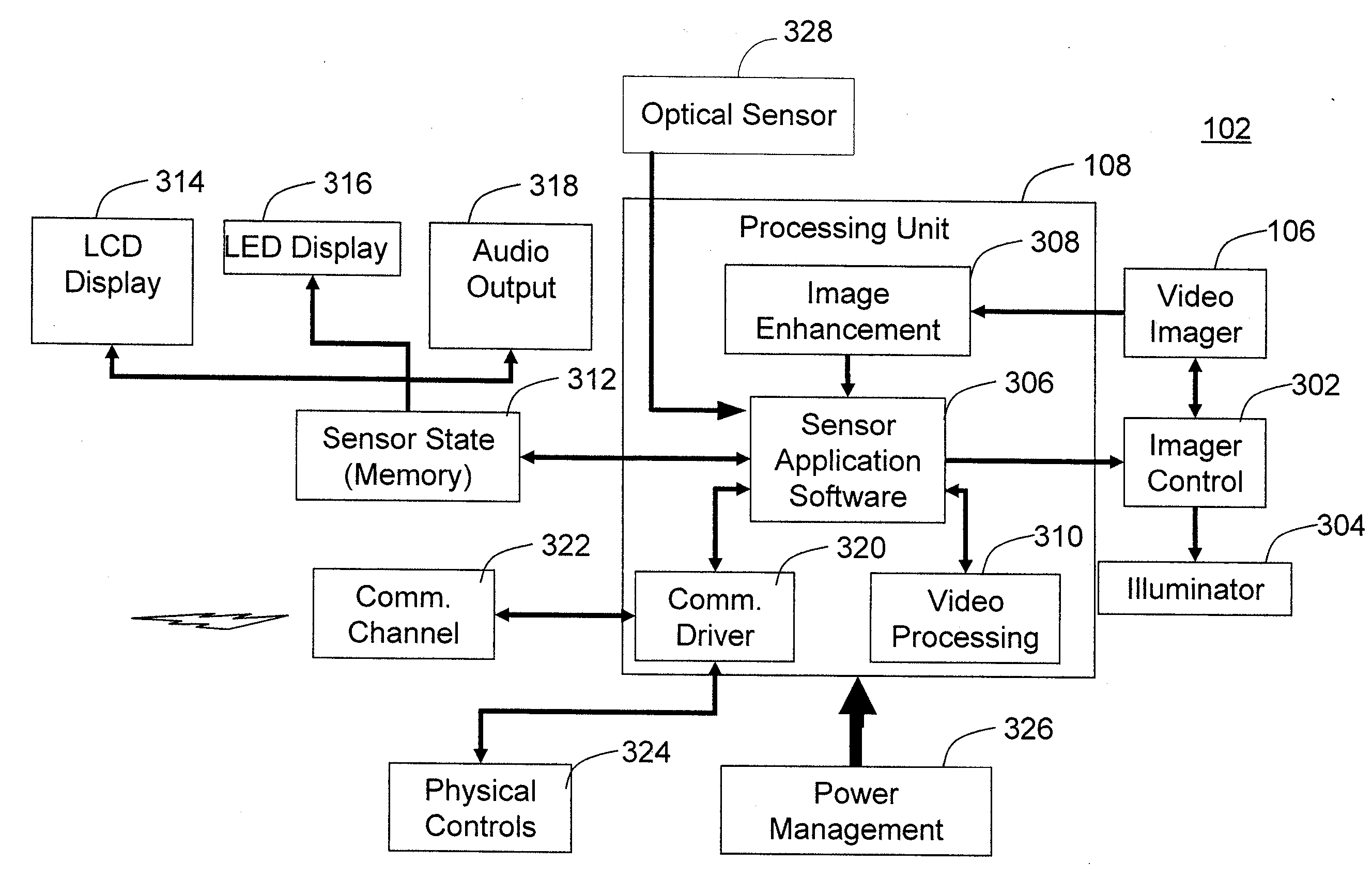
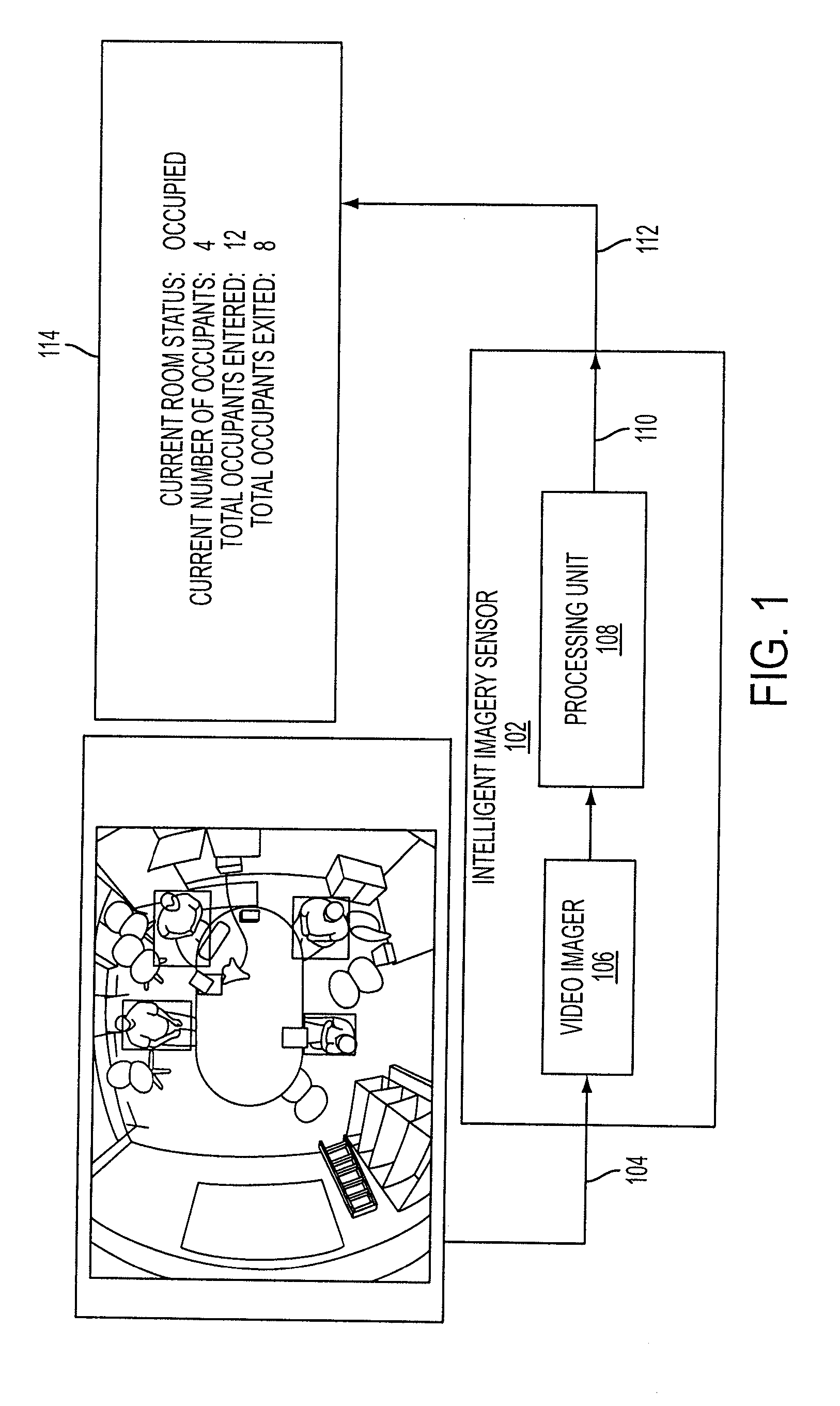
[0032]FIG. 1 depicts a high-level block diagram of a sensor according to an exemplary embodiment. In an exemplary embodiment, an intellig...


PUM


Abstract

A sensing device includes: a video imager to obtain video of an area; a processing unit to receive and process the video from the video imager to identify one of an event or a datum of interest; and a communication channel to output a non-imagery signal representing the event or datum.

Description

CROSS-REFERENCE TO RELATED APPLICATIONS [0001] This application is a non-provisional application claiming priority to U.S. Provisional Application No. 60 / 802,764, filed May 24, 2006, entitled “Intelligent Imagery-Based Sensor,” the contents of which are incorporated herein in their entirety.FIELD OF THE INVENTION [0002] The present invention relates to sensor technologies for residential, commercial, and public space monitoring. BACKGROUND OF THE INVENTION [0003] This invention relates generally to sensing and monitoring of human space. Embodiments of the invention may include a sensor device that uses a video imager combined with a processor and intelligent image processing software to determine the presence of an activity or a condition in a scene being monitored. For example, the sensor can be used to detect the presence or absence of one or more people, a count of people in one or more areas, or a specific activity within one or more areas. SUMMARY OF THE INVENTION [0004] In an ...

Claims


Application Information

Patent Timeline
IPC IPC(8): H04N7/18
CPCG08B13/1961G08B13/19613G08B13/19652H04N7/18G08B13/19686G08B13/19689H04N5/225G08B13/19663H04N23/00
Inventor LIPTON, ALAN J.THOMPSON, BRUCECLARK, JOHN I.W.VENETIANER, PETER L.ZHANG, ZHONGYU, LIYIN, WEI HONGTITUS, STEVEMISTRY, AMITMORRIS, JAMES
Owner MOTOROLA SOLUTIONS INC
Why Eureka
Try Eureka