Display Apparatus

a display device and display screen technology, applied in the field of display devices, can solve the problems of low water resistance of the sealing glass of a low melting point, and the inability to resist water, etc., to achieve high yield, high bonding strength, and high durability

Active Publication Date: 2007-12-13
PANASONIC LIQUID CRYSTAL DISPLAY CO LTD
View PDF2 Cites 30 Cited by
  • Summary
  • Abstract
  • Description
  • Claims
  • Application Information

AI Technical Summary

Benefits of technology

[0016] The use of the bonding material in accordance with the present invention can provide a display apparatus that has a sealing portion with a high bonding strength, high durability, and high yield. Further, the bonding material in accordance with the present invention has an advantage of avoiding environmental pollution due to lead and reduction of vacuum due to devitrification in the sealing process. Furthermore, since the bonding material in accordance with the present invention can improve the water- and moisture-resistances of the sealed areas, the reduction of vacuum due to deterioration of the sealing portion can be prevented.

Problems solved by technology

However, since lead (Pb) is poisonous, lead-free glasses have been widely used.
However, the water resistance of the sealing glass of a low melting point is low.
Accordingly, the sealed part of a high-vacuum space may be corroded in the surfaces that are in contact with the atmosphere and the vacuum may be weakened.
Similarly, lead-free sealing glasses are not resistant to water, either.
Further, if the sealing glass is kept at a high sealing temperature for long time, the glass becomes easily crystallized and less flowable.
In extreme cases, bonding may be disabled.
When devitrified, the glass loses its sealing fluidity and cannot fit in the whole bonded area.
Consequently, the glass cannot accomplish the sealing purpose.

Method used


Image

  • Display Apparatus
  • Display Apparatus
  • Display Apparatus

Examples


embodiment 1

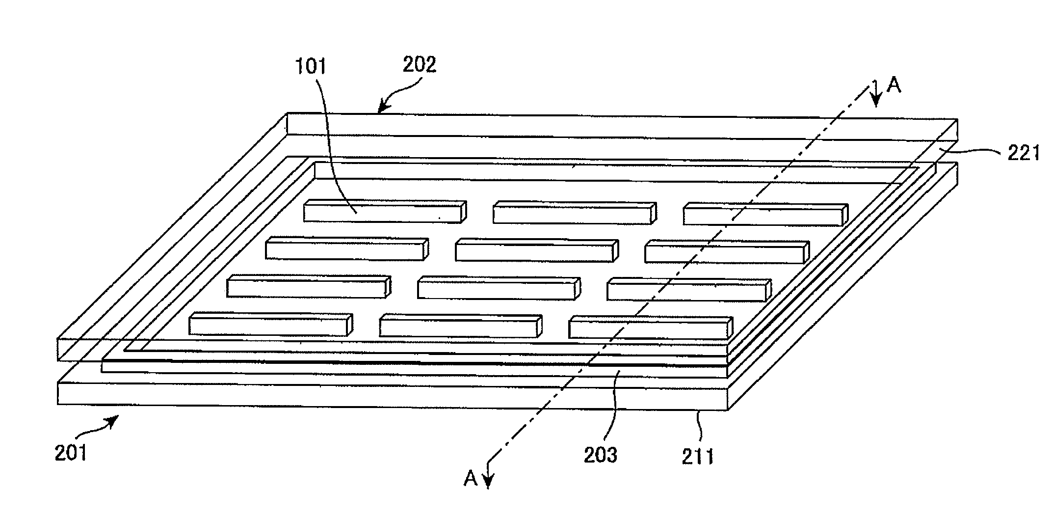
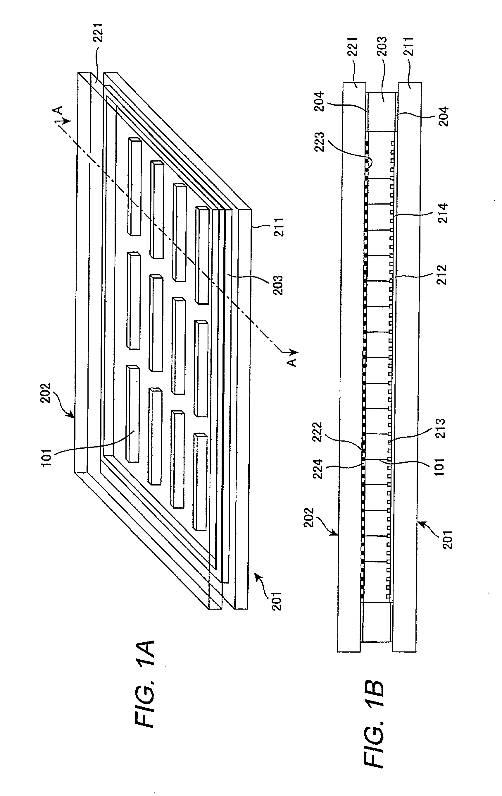
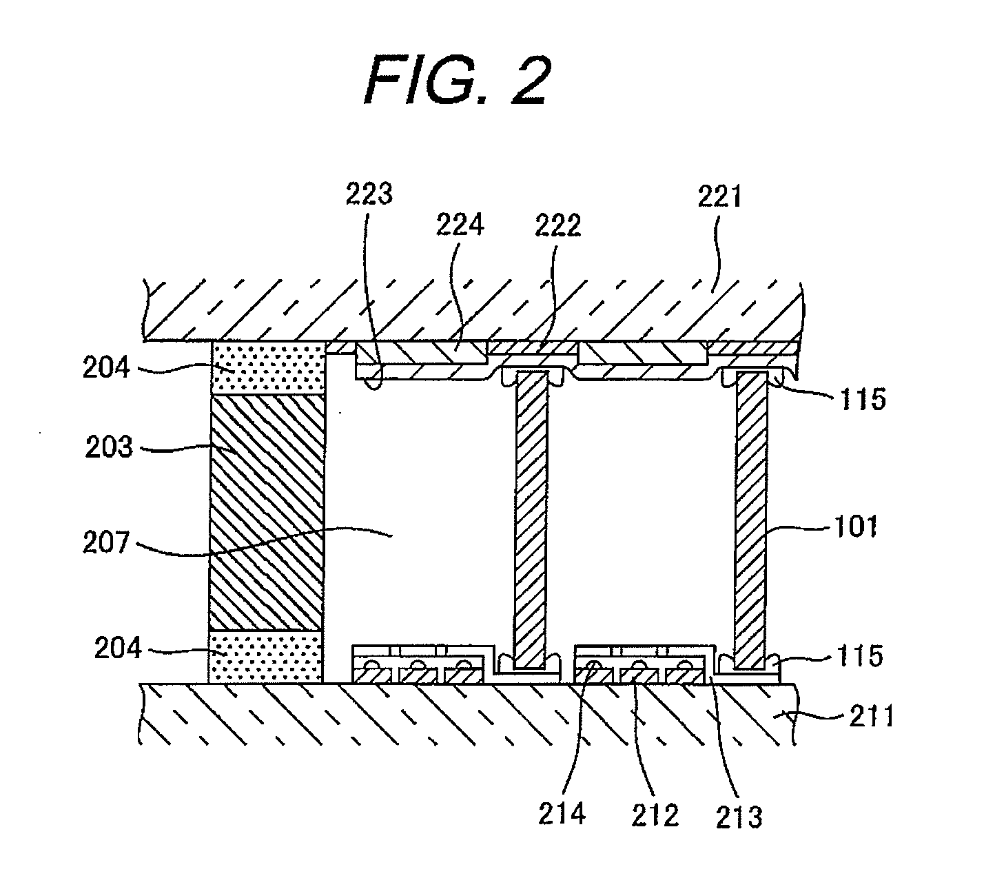
[0063] Embodiments 1 to 3 are examples of increasing the water resistance of the bonding material and improving its durability. These embodiments will be explained in detail referring to the drawings below. FIG. 3 is a schematic plane view to explain the structure of a flat-panel display apparatus. This display apparatus example uses an MIM (Metal-Insulator-Metal) type electron source.

[0064] By the way, in addition to the display apparatus of this embodiment, the present invention can also be applied to various kinds of display apparatus and field emission type display apparatus that use wire-formed glass plates such as electrons emission type that use thin-film electron sources and plasma display apparatus. Further, the present invention is not limited to structural materials such as substrates for flat-panel display apparatus and their bonding and vacuum-sealing material. The present invention can also be applied to glass structural members for electronic apparatus such as magnet...

embodiment 2

[0107] To lower the melting point of the glass bonding material in accordance with the present invention, various additive materials were searched and studied. The compositions of SPL-27 as a representative sample were selected in the above embodiment. Ag2O, Cu2O, Cs2o, HfO2, Na2O, K2O and / or TeO2 was added to the powder mixture of glass materials while changing the rates of the added compound, and checked how their glass transition points changed. As seen from FIG. 6 which lists the test results, we found that additives of Ag2O, Cu2O, Cs2O, HfO2, Na2O, K2O, and TeO2 respectively have an effect to lower the transition point of the glass bonding material in accordance with the present invention. By the way, when the additives are added too much, crystals are deposited in the glass. Accordingly, it is preferable that the rate (% by weight) of the additives is 1 to 10%. It is assumed that, when an additive material is added too much, the relative ratios of vanadium and phosphorus becom...

embodiment 3

[0108]FIG. 7 is a cross-sectional schematic diagram to explain the structure of a plasma display apparatus.

[0109] The plasma display apparatus of Embodiment 3 of this invention is equipped with rear substrate SUB1 and front substrate SUB2 which are oppositely faced and bonded at their peripheries with bonding material F that uses the glass composition of this embodiment. The front substrate is equipped with discharge electrodes H and the rear substrate is equipped with address electrodes A. These electrodes are protected by a protective layer. Rib spacers SPC are disposed among pixels and work as partition walls to keep an appropriate clearance (space) between the front and rear substrates. Each pixel contains fluorescent materials PH of three colors (red, green, and blue). This embodiment prepares the ribs with a glass composition that satisfies the composition range of a glass bonding material that contains Ba and Sb of the above specified ratios. This glass excels at resistance ...


PUM

PropertyMeasurementUnit
mean particle sizeaaaaaaaaaa
particle sizeaaaaaaaaaa
sizeaaaaaaaaaa

Abstract

A sealing glass of a low melting point glass composition which is a phosphate glass that contains transition metal wherein the glass contains 15 to 35% of BaO and Sb2O3 (in total) and the ratio by weight of BaO to Sb2O3 or Sb2O3 to BaO is 0.3 or less. Particularly the transition metal is vanadium and the glass contains V2O5 of 45 to 60 wt % as vanadium oxide and P2O5 of 15 to 30 wt % as phosphorus oxide.
The bonding material is a mixture of a filler and a vanadate-phosphate glass that contains V2O5 as the main ingredient and the glass contains V2O5 of 45 to 60%, P2O5 of 20 to 30%, BaO of 5 to 15%, TeO2 of 0 to 10%, Sb2O3 of 5 to 10%, and WO3 of 0 to 5%. The particle size of the filler is in the range of 1 to 150 μm and the ratio of filler is 80% by volume or less of the adhesive glass.

Description

CLAIM OF PRIORITY [0001] The present application claims priority from Japanese applications serial No. 2006-154861, filed on Jun. 2, 2006 and serial No. 2007-20308, filed on Jan. 31, 2007, the contents of which are hereby incorporated by reference into this application. BACKGROUND OF THE INVENTION [0002] The present invention relates to an image display apparatus equipped with a vacuum space and to a glass bonding material for sealing or glass composition for sealing used to produce the display apparatus. BACKGROUND ART [0003] Recently, information processing apparatus or television apparatus have a tendency to use extended definition functions. So, flat panel display (FPD) apparatus have been in the spotlight since they have high-brilliance and high-fineness characteristics, light-weight and can be down-sized. A typical flat panel display (FPD) apparatus are liquid crystal display apparatus, plasma display apparatus, and electrons emission type image display apparatus. Further, fie...

Claims


Application Information

Patent Timeline
Patent Type & Authority Applications(United States)
IPC IPC(8): B29D22/00
CPCC03C3/21G02F1/1339G09G3/22Y10T428/131G09G2300/0439Y10T428/10Y10T428/1059G09G3/2983C09K2323/00C09K2323/05
Inventor SAWAI, YUICHISHIONO, OSAMUNAMEKAWA, TAKASHINAITOU, TAKASHIHAYASHIBARA, MITSUOKIJIMA, YUICHIHIRASAWA, SHIGEMIASAKURA, SHUNICHIYAMAMOTO, HIROKIHATORI, AKIRA
Owner PANASONIC LIQUID CRYSTAL DISPLAY CO LTD
Why Eureka
Try Eureka