
Stapling Device

a technology of stapling device and stapler, which is applied in the direction of surgical staples, oesophagoscopes, paper/cardboard containers, etc., can solve the problems of preventing the complete bending of the articulation section, creating play between the vertebrae, and difficulty in aligning the parts of the stapler

Active Publication Date: 2008-01-03
MEDIGUS LTD
View PDF15 Cites 126 Cited by
  • Summary
  • Abstract
  • Description
  • Claims
  • Application Information

AI Technical Summary

Benefits of technology

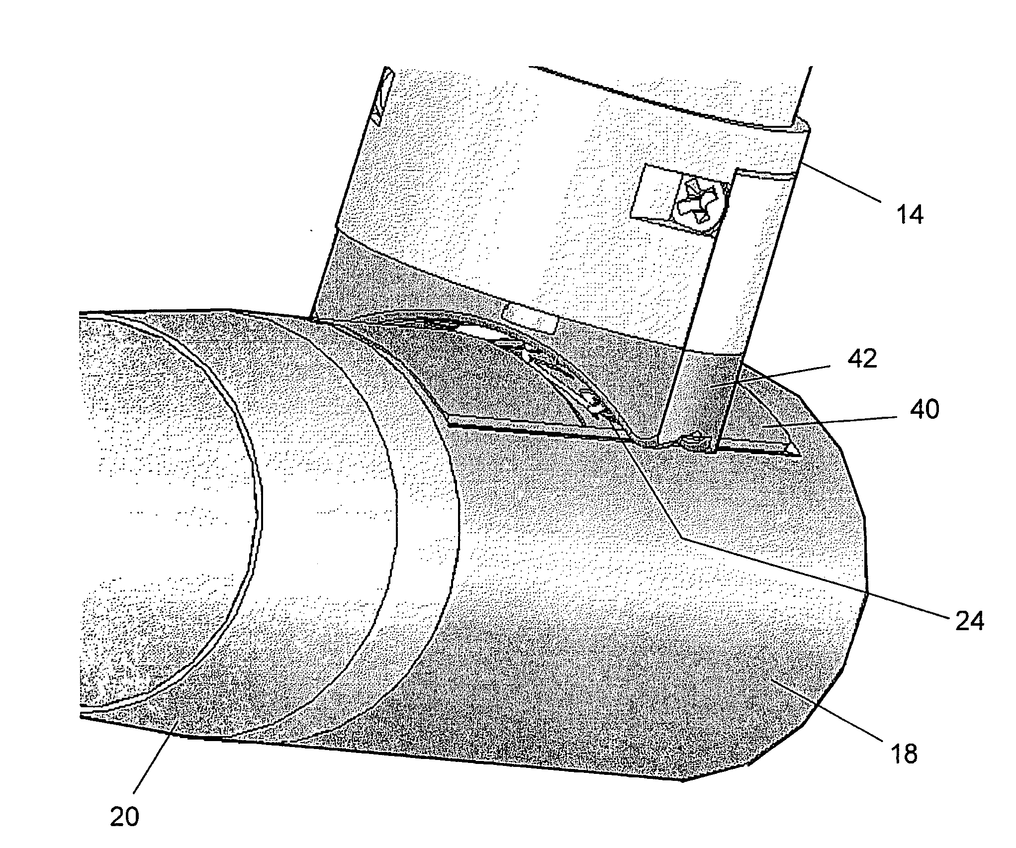
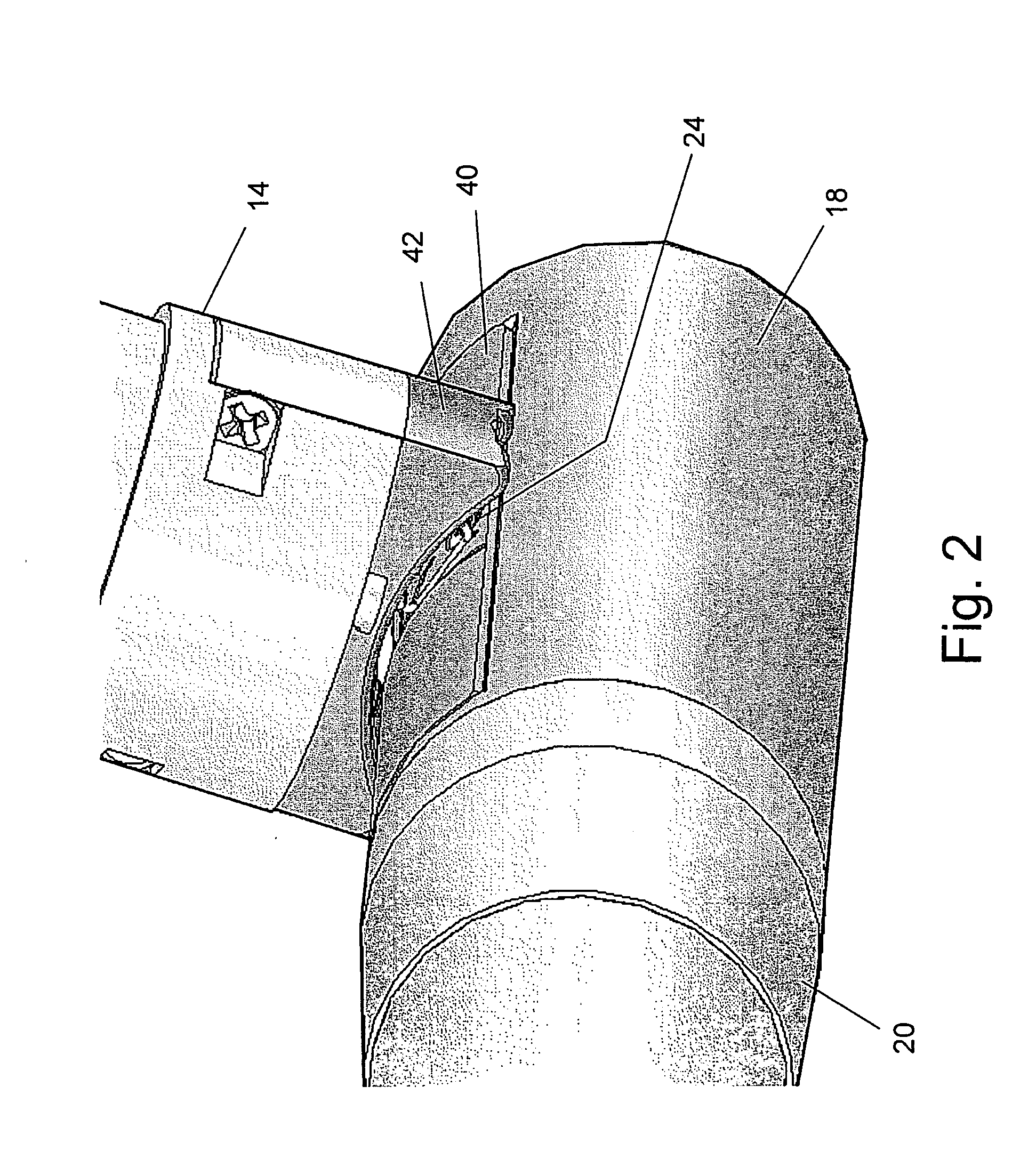
[0015]In a first aspect the present invention is directed towards providing a stapling device comprised of an articulation section, a staple cartridge containing staples and parts of a staple-firing mechanism, and an anvil portion. The cartridge is located at one end of the articulation section and the anvil portion is located at the other end. The front surfaces of the anvil and the cartridge are curved. When the articulation section is bent, bringing the curved front surfaces of said anvil and the cartridge opposite each other, the curved surfaces help to correct transverse misalignment and to bring the anvil and the cartridge into the correct working relationship.
[0018]The face of the cartridge is comprised of a curved surface having a curvature that must match the curvature of the front face of the anvil. The face of the cartridge can be comprised of a single curved surface. In a preferred embodiment, the center of curvature of the cartridge face in the area of the array is lowered relative to the center of curvature of the rest of the surface. This results in a cartridge having a surface comprised of two levels. The presence of the two levels assists in correcting longitudinal misalignment.

Problems solved by technology

Consequently, at the time the staples are fired, the anvil and the head must be clamped rigidly together, or the force will cause them to separate, and the staples will not fully close.
However it has been found by the inventors of the current invention, that even with the most accurate articulation section, difficulties arise in aligning the parts of the stapler.
There are two main reasons for these difficulties: firstly, as a result of repeated bending and unbending of the articulation section, wear of the parts takes place resulting in the creation of play between the vertebrae; secondly, when using the device within a body, foreign objects can enter the spaces between the vertebrae, preventing the complete bending of the articulation section.

Method used


Image

  • Stapling Device
  • Stapling Device
  • Stapling Device

Examples


Embodiment Construction

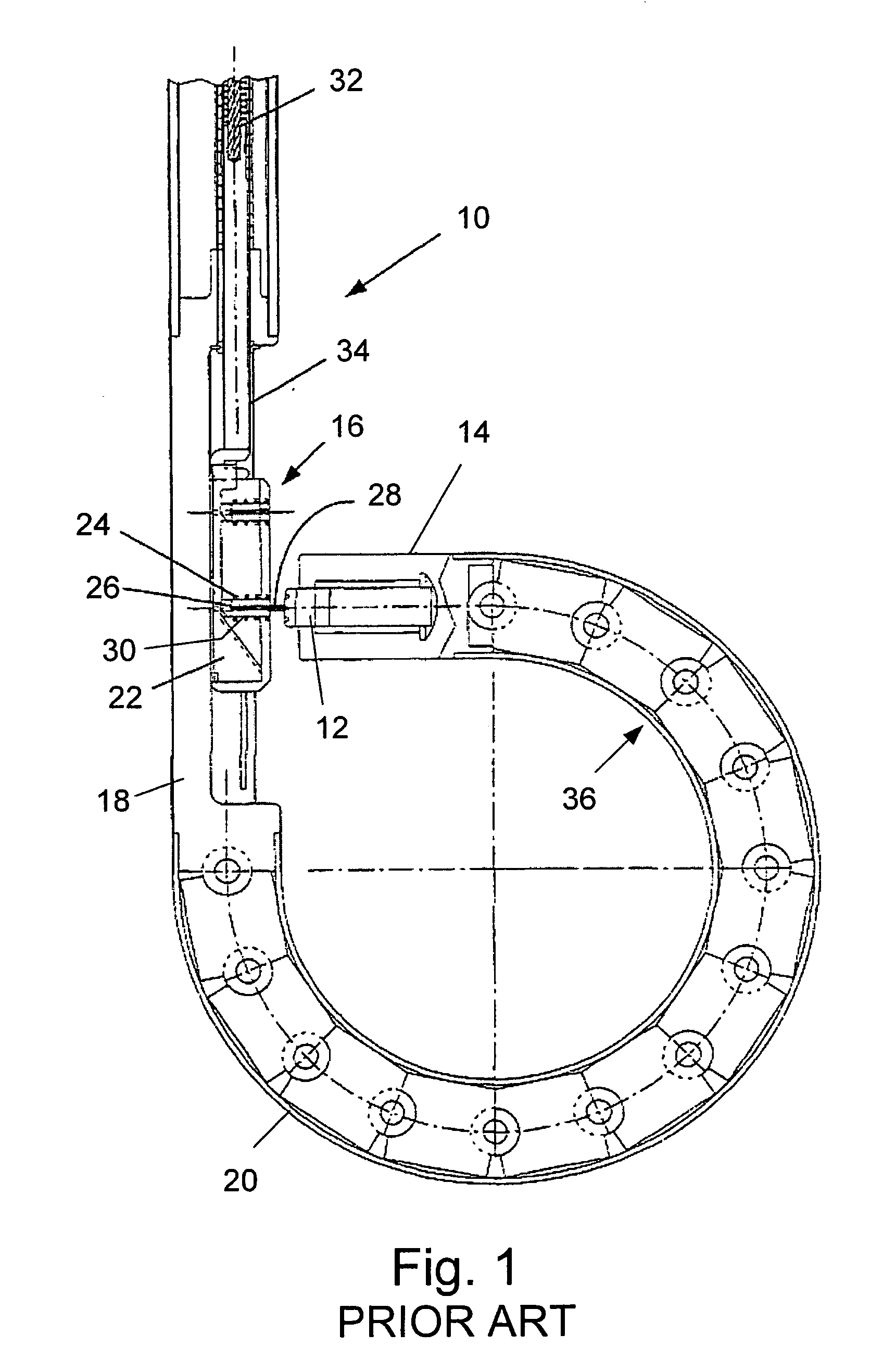
[0031]FIG. 1 is a schematic cross-sectional view of the distal section of an endoscope 10 comprising the stapler device disclosed in the above referenced WO 02 / 39909. In the figure is shown the anvil section 12, located in the distal tip 14 of the endoscope and the stapler cartridge 16, located in rigid section 18. Between distal tip 14 and rigid section 18 is located the articulation section 20. Parts of the stapler cartridge shown in FIG. 1 and described in WO 02 / 39909 are: one of the firing cams 22, a staple 24, and the corresponding staple pusher 26. One of the screws 28 is shown screwed out of its storage space in anvil 12 and into a receptacle 30 in cartridge 16 in order to enable the stapling to be carried out. Numeral 32 designates the firing cable that is attached to plunger 34 that is in turn connected to the cams in the staple cartridge.

[0032]As described in WO 02 / 39909 with reference to the GERD procedure, the endoscope is inserted into the patient's stomach through the ...


PUM

PropertyMeasurementUnit
Areaaaaaaaaaaa
Distanceaaaaaaaaaa

Abstract

The invention is a stapling device comprised of an articulation section having a staple cartridge containing staples and parts of a staple-firing mechanism located at one end and an anvil portion located at the other end. The front surfaces of the anvil and the cartridge are curved. When the articulation section is bent the curved front surfaces of the anvil and the cartridge are brought opposite each other. As the distance between said curved surfaces is reduced, their curvature helps to correct transverse misalignment and to bring the anvil and the cartridge into the correct working relationship.

Description

FIELD OF THE INVENTION[0001]The present invention relates to stapling devices. Specifically the invention relates to a stapling device comprised of a stapler cartridge comprising a supply of staples and parts of a staple firing mechanism, which is attached to one end of an articulation section, and an anvil portion, which is attached to the other end of the articulation section.BACKGROUND OF THE INVENTION[0002]In recent years, surgeons have been increasingly using surgical staples instead of sutures. Surgical staples and surgical stapling instruments have made many difficult procedures much simpler to perform, and significantly reduced the time required to perform them, thus allowing the patient to spend less time under general anesthesia.[0003]In general, modern surgical stapling instruments for use on internal organs and tissues are comprised of a head containing a cartridge which holds the staples and a mechanism for ejecting the staples out of the cartridge, either sequentially ...

Claims


Application Information

Patent Timeline
IPC IPC(8): B27F7/17A61B1/005A61B1/273A61B17/00A61B17/068A61B17/072A61B19/00
CPCA61B1/0051A61B1/2736A61B17/0686A61B17/072A61B17/07207A61B2019/304A61B2017/003A61B2017/00827A61B2017/07214A61B2017/07221A61B2017/07278A61B2017/00106A61B2090/034A61B17/068
Inventor SONNENSCHEIN, MINELUSONNENSCHEIN, ELAZARGOVRIN, AMIR
Owner MEDIGUS LTD
Learn More