Off-Axis Angle Estimation Method and Apparatus Using the Same

a technology of off-axis angle and estimation method, applied in the field of error estimation technologies, can solve the problems of poor initial work accuracy, incorrect azimuthal angle of radar reflector obtained as a result of processed radar signals, and misalignment of reference axis with actual use, and achieve the effect of stably achieving off-axis angle estimation

Active Publication Date: 2008-01-17
MITSUBISHI ELECTRIC CORP
View PDF1 Cites 43 Cited by
  • Summary
  • Abstract
  • Description
  • Claims
  • Application Information

AI Technical Summary

Benefits of technology

[0012] As described above, according to an off-axis angle estimation method in the present invention, firstly, based on observed values by a radar device, a plurality of reflection points having approximately equal relative-velocity components in the traveling direction of a vehicular object is found out. Secondly, an off-axis angle of the radar is sought by combining only the relative-velocity components along the line of radar sight and azimuthal angles at the plurality of reflection points found out in this manner. In this process, data such as the traveling velocity and velocity-error magnification of the vehicular object mounted with the radar device is not used. Therefore, even in cases in which the traveling velocity of the vehicular object mounted with a radar device can not be obtained, it becomes possible to stably achieve off-axis angle estimation.

Problems solved by technology

In these radar devices, because a radar reference axis becomes misaligned off an originally presumed direction, a problem can be raised in that an azimuthal angle with respect to a radar reflector obtained as a result of processed radar signals becomes not correct.
These kinds of offsets of the reference axis are caused by poor accuracy of an initial work done when a radar device is mounted on a vehicular object.
Moreover, even if at an initial stage the radar device is mounted on the vehicular object with high accuracy, there exist cases in which the reference axis becomes misaligned with actual use.
Because, correctly observed values can not be obtained from the radar device under a state in which the reference axis becomes misaligned, contribution to increased safety can not be made.

Method used


Image

  • Off-Axis Angle Estimation Method and Apparatus Using the Same
  • Off-Axis Angle Estimation Method and Apparatus Using the Same
  • Off-Axis Angle Estimation Method and Apparatus Using the Same

Examples


embodiment 1

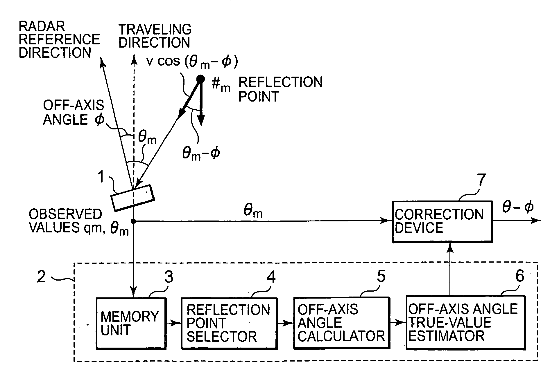
[0028] To begin with, the operating principles of an off-axis angle estimation method in Embodiment 1 of the present invention are explained. FIG. 1 is a conceptual diagram for explaining the operating principles in Embodiment 1 of the present invention. In FIG. 1, a radar device 1 is, for example, a radar device mounted on a vehicular object such as a motor vehicle. Moreover, a reflection point 1 and a reflection point 2 are points of reflecting radar waves, detected by the radar device 1.

[0029] The radar device 1 is provided for detecting other vehicles exist in a traveling direction of the vehicular object, and obstacles such as road installation facilities. When the radar device 1 detects obstacles and / or other vehicles, the detected result is outputted to devices that are external to the radar device 1, for example, to a vehicular clearance maintaining device, an adaptive cruise control device, and the like, which are provided for uses such as velocity controls and increased s...

embodiment 2

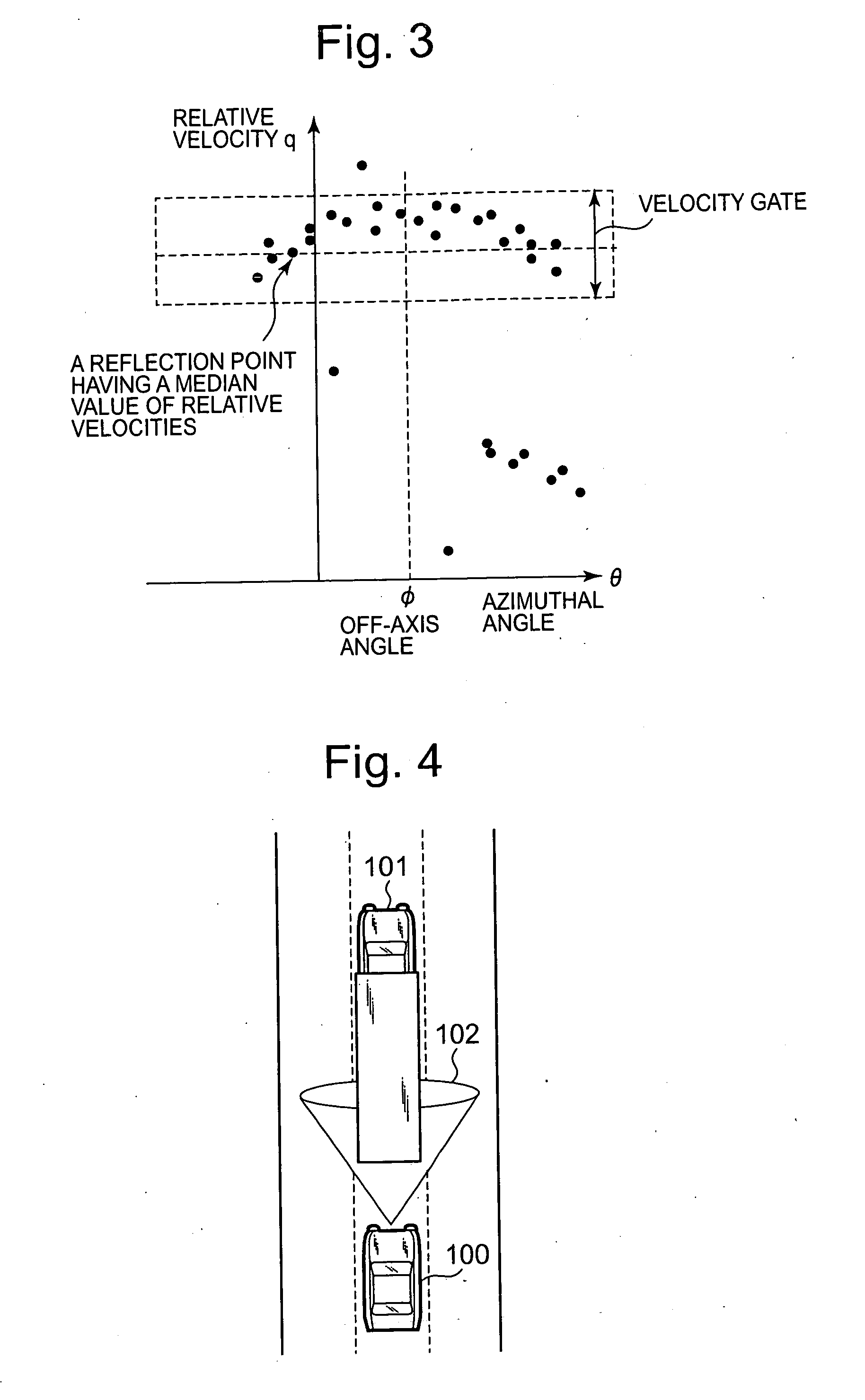
[0068] In the off-axis angle estimation device in Embodiment 1, reflection points are selected to have a median value of relative velocities as a reference velocity; however, instead of taking this manner, a reflection point having a maximum value among the relative velocities can be selected as the reference velocity. Namely, by assuming that the reflection point having the maximum value among the relative velocities is a reflection point on a road surface, a velocity gate (a range of values in which difference among the relative velocities to each other becomes within a predetermined value) is determined with reference to the relative velocity at the reflection point. Then, the reflection point selector 4 is allowed to select a plurality of reflection points that is included in the velocity gate.

[0069] For example, there may be an instance in which motor vehicles and the like driving on an express way have a velocity difference to a road surface that is significantly greater than...

embodiment 3

[0074] In the off-axis angle estimation method in Embodiment 1 or Embodiment 2, a configuration has been made in which a relative velocity at any one of reflection points is specified as the reference velocity, and reflection points are then selected so that relative velocities are included in a range of values having a predetermined width centering on the reference velocity. Instead of taking this manner, by finding a range of values in which a frequency becomes a predetermined number or greater in distribution of relative velocities, and by determining the range of values as a velocity gate, the reflection point selector 4 is allowed to select reflection points that are included in this range of values.

[0075] Equation (3) holds between two of the reflection points at which the relative-velocity components in the traveling direction of a vehicular object are approximately equal to one another. Therefore, not necessarily limited to reflection points on a road surface, it can be rea...


PUM


Abstract

Without using a traveling velocity of a vehicular object mounted with a radar device, an off-axis angle which is an offset angle between a reference direction of the radar device and a traveling direction of the vehicular object is estimated. An off-axis angle estimation method for estimating an off-axis angle (φ) of a radar device (1) mounted on the vehicular object having a predetermined traveling direction includes that, from among reflection points of which a relative-velocity component (q) along the line of radar sight and an azimuthal angle (θ) are detected by the radar device (1), a plurality of reflection points of which the relative-velocity components in the traveling direction of the vehicular object being approximately equal to one another is selected without using the traveling velocity of the vehicular object; and based on the relative-velocity components along the line of radar sight, and on the azimuthal angles, of the plurality of reflection points having been selected, the off-axis angle (φ) is autonomously calculated solely from the observed values based on radar waves.

Description

TECHNICAL FIELD [0001] The present invention relates to error estimation technologies of an offset angle (an “off-axis angle,”“alignment offset angle”) to a reference direction of a radar utilizing reflections of propagating waves such as radio waves, sound waves, and light waves, in particular, to an estimation technology of the offset between a reference axis of the radar used for detecting radar reflectors in a frontal direction of a vehicular object (a traveling direction of the vehicular object), and the frontal direction of the vehicular object. BACKGROUND ART [0002] Recently, by mounting radar devices on vehicular objects such as motor vehicles, and by detecting radar reflectors such as obstacles in traveling directions, developments are carried out so as to realize those functions for velocity controls and collision prevention. In these radar devices, because a radar reference axis becomes misaligned off an originally presumed direction, a problem can be raised in that an az...

Claims


Application Information

Patent Timeline
Patent Type & Authority Applications(United States)
IPC IPC(8): G01S7/40G01S13/93G01S13/931
CPCG01S7/4026G01S13/931G01S2007/403G01S2013/9339G01S2013/9321G01S2013/9325G01S2007/4091G01S2013/9329G01S7/403G01S7/4091
Inventor OKAMURA, ATSUSHIHARA, ROKUZOUWAKAYAMA, TOSHIOHIRAI, TOSHIYUKI
Owner MITSUBISHI ELECTRIC CORP
Why Eureka
Try Eureka