Eureka AIR delivers breakthrough ideas for toughest innovation challenges, trusted by R&D personnel around the world.

Geometric shaped side bearing pad

a bearing pad and geometries technology, applied in the field of bearings, can solve the problems of high speed derailment and rapid wear of truck components, and achieve the effect of providing lateral stiffness

Inactive Publication Date: 2008-01-31
CHEMTURA CORP
View PDF21 Cites 7 Cited by
  • Summary
  • Abstract
  • Description
  • Claims
  • Application Information

AI Technical Summary

Benefits of technology

[0008]Accordingly, it is an object of the present invention to provide a geometric shaped side bearing pad for any suspension or spring application for which energy needs to be absorbed while controlling the maximum reaction force, such as side bearers, dock fendering, ride bumpers, certain impact bumpers, etc. The bearing pad may be used with many existing bearing boxes that previously held other types of bearing pads, such as the rubber metal sandwich pad. The bearing pad provides a non-linear spring rate that levels out the reaction force without buckling. The bearing pad does not need bonding.
[0011]The angle ? can be within the range of about 20 degrees and 85 degree and, may preferably be within the range of about 30 degrees and 75 degrees. The top of the bearing pad can have a slot defined therethrough to accommodate a protrusion in a fixture to engage the bearing pad. The bearing pad can provide a friction contact with an object and enables lateral force transfer to the bearing pad, thereby providing lateral stiffness. The bearing pad can include polyurethane, such as thermoset polyurethane, thermoplastic polyurethane, or a two part castable urethanes made from polyether-isocyanate or polyester-isocyanate prepolymers cured with organic diamine or polyol materials.

Problems solved by technology

Truck hunting occurs during movement of a rail car over tracks or rails and is caused mainly by worn wheels and / or worn rail.
Truck hunting can lead to rapid truck component wear and can cause high speed derailments.

Method used


Image

  • Geometric shaped side bearing pad
  • Geometric shaped side bearing pad
  • Geometric shaped side bearing pad

Examples


Embodiment Construction

[0017]Hereinafter, preferred embodiments according to the present invention will be described with reference to the accompanying drawings. The same reference numerals are used to designate the same elements as those shown in other drawings. In the following description, a detailed description of known functions and configurations incorporated herein will be omitted when it may obscure the subject matter of the present invention.

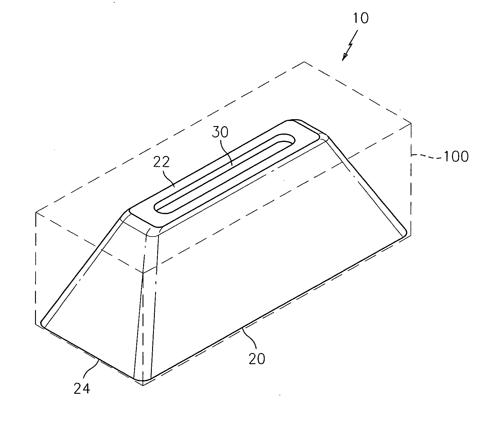
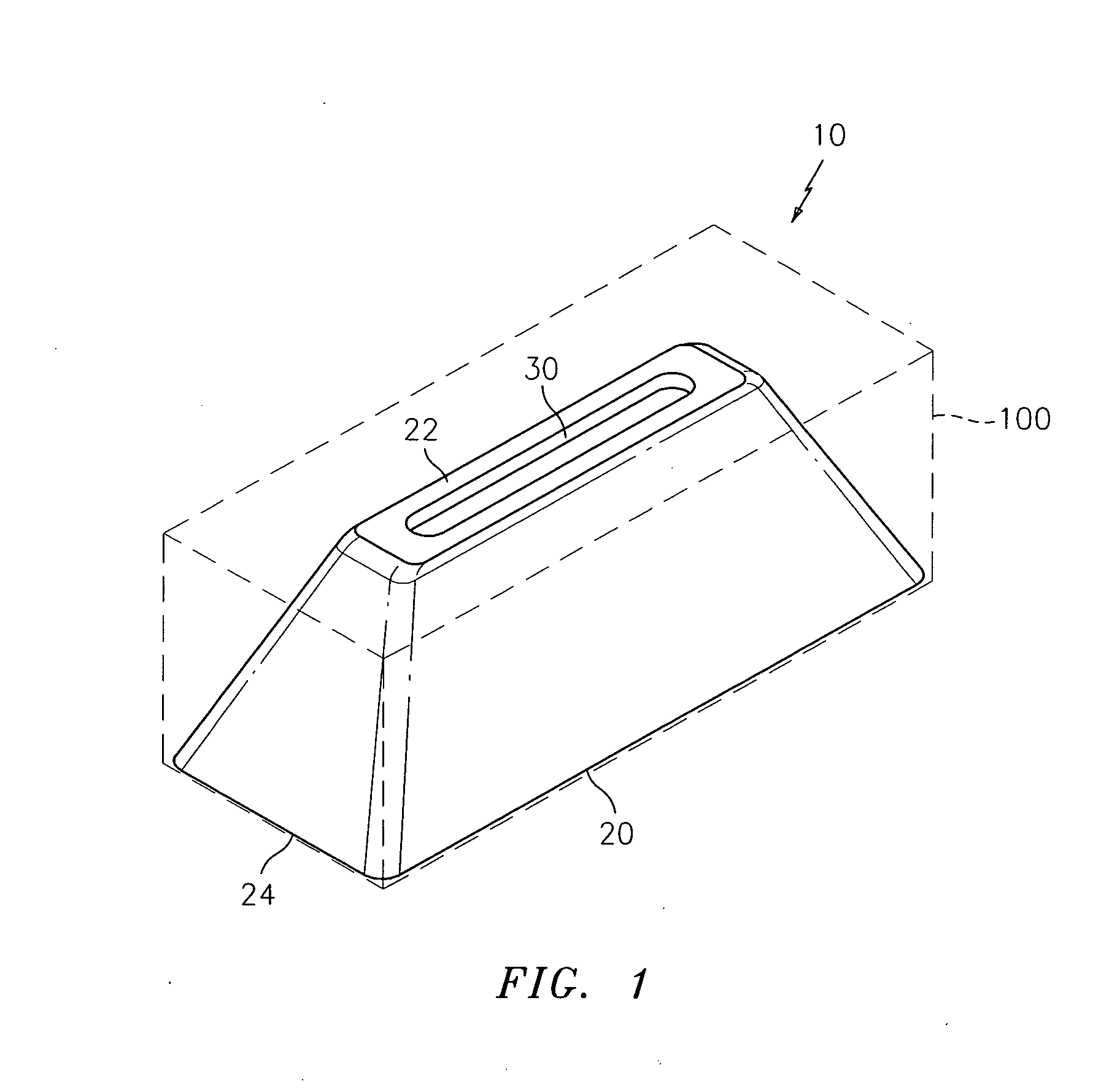
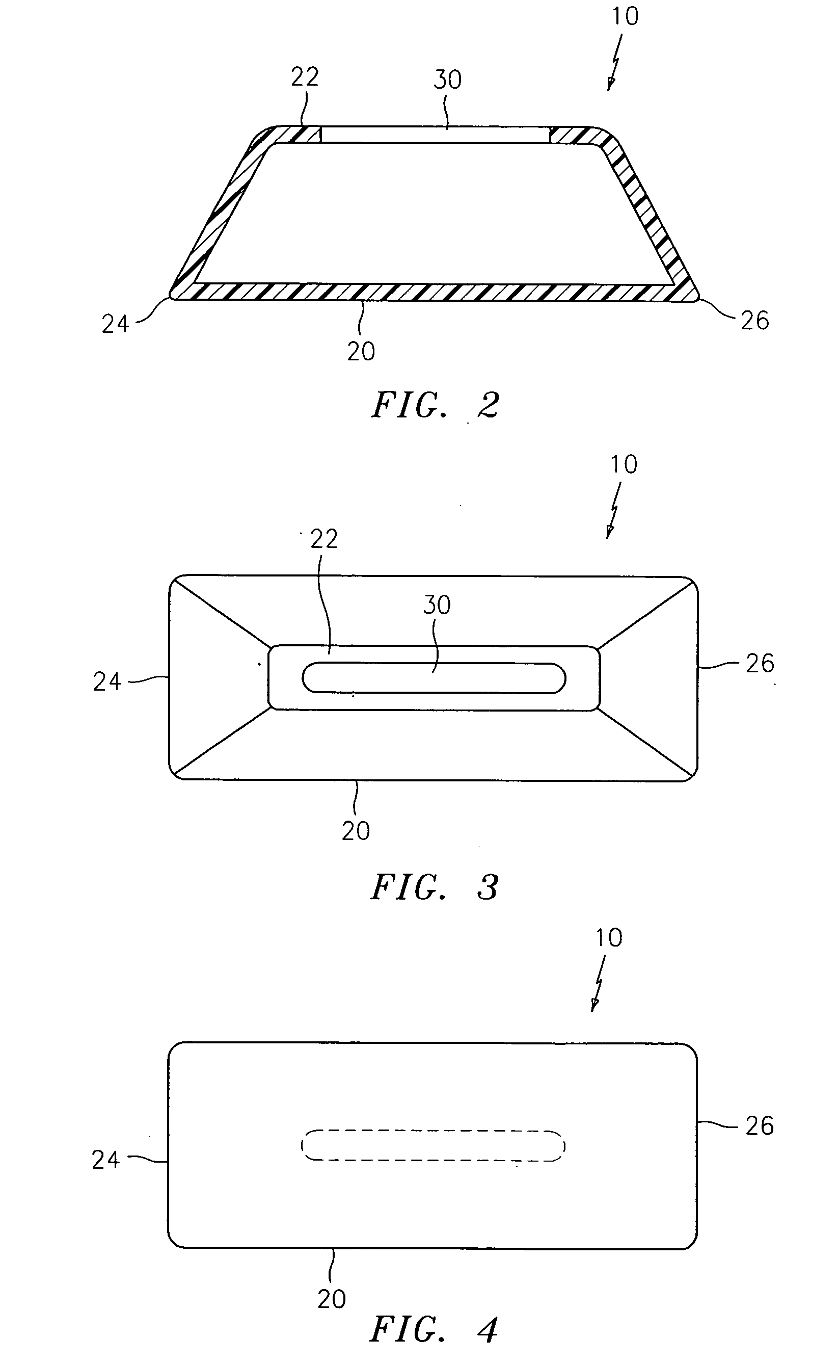
[0018]Referring to the drawings, FIGS. 1-4 show a geometric shaped side bearing pad 10 according to the present invention. As shown in FIG. 1, the bearing pad 10 is contained within a bearing box 100 which forms no part of the invention. The geometric shape of the bearing pad can be a pyramid shape, a conical shape, a trapezoidal shape, a prismoid shape, etc. For example, as a pyramid shape, as shown in the drawings, the surface of the bearing pad 10 can have two or four sides, and can have spacing within the surface, or can be solid. The surface of the beari...


PUM


Abstract

A geometric shaped side bearing pad includes a top and a surface extending an angle ? towards the top, wherein the bearing pad has a geometric shape and a non-linear spring rate which levels out a reaction force without buckling. The surface of the bearing pad can have two sides or four sides, can have spacing within the surface, or can be solid. The angle ? can be within the range of about 20 degrees and 85 degree and, may preferably be within the range of about 30 degrees and 75 degrees. The top of the bearing pad can have a slot defined therethrough to accommodate a protrusion in a fixture to engage the bearing pad. The bearing pad can provide a friction contact with an object and enables lateral force transfer to the bearing pad, thereby providing lateral stiffness.

Description

BACKGROUND OF THE INVENTION[0001]1. Field of the Invention[0002]The present invention generally relates to bearings and, more particularly, to a geometric shaped side bearing pad.[0003]2. Description of the Related Art[0004]Rail cars are typically equipped with wheeled trucks including side bearings that are adapted, for example, to absorb energy in response to large impact loads, to control or restrict hunting movements of the rail cars, to decrease warping tendencies of the rail cars, to provide better curving characteristics of the rail cars, etc. Truck hunting occurs during movement of a rail car over tracks or rails and is caused mainly by worn wheels and / or worn rail. Truck hunting can lead to rapid truck component wear and can cause high speed derailments.[0005]Side bearing developments to reduce or otherwise control adverse truck action have been ongoing for years. For example, side bearings have been developed with various types of springs, hydraulics dampers, yaw dampers, ...

Claims


Application Information

Patent Timeline
Patent Type & Authority Applications(United States)
IPC IPC(8): B61F3/00
CPCB61F5/142F16F1/373F16F2230/007F16F1/44F16F1/422
Inventor PALINKAS, RICHARD L.
Owner CHEMTURA CORP
Why Eureka
Eureka Blog
Learn More