Electronic still camera with capability to perform optimal focus detection according to selected mode

a technology of optimal focus detection and still camera, applied in the field of still camera, can solve the problems of slow operation, image obtained by other operations than imaging operations cannot be displayed on the lcd monitor,

Inactive Publication Date: 2008-03-06
OLYMPUS CORP
View PDF21 Cites 45 Cited by
  • Summary
  • Abstract
  • Description
  • Claims
  • Application Information

AI Technical Summary

Problems solved by technology

While contrast AF does not require a special optical system or sensor, it suffers a slow operation because it seeks a focus point while driving the lens.
Because the quick return mirror and sub mirror are located between the imaging device and the imaging lens, however, an image obtained by other operations than an imaging operation cannot be displayed on the LCD monitor.

Method used


Image

  • Electronic still camera with capability to perform optimal focus detection according to selected mode
  • Electronic still camera with capability to perform optimal focus detection according to selected mode
  • Electronic still camera with capability to perform optimal focus detection according to selected mode

Examples


first embodiment

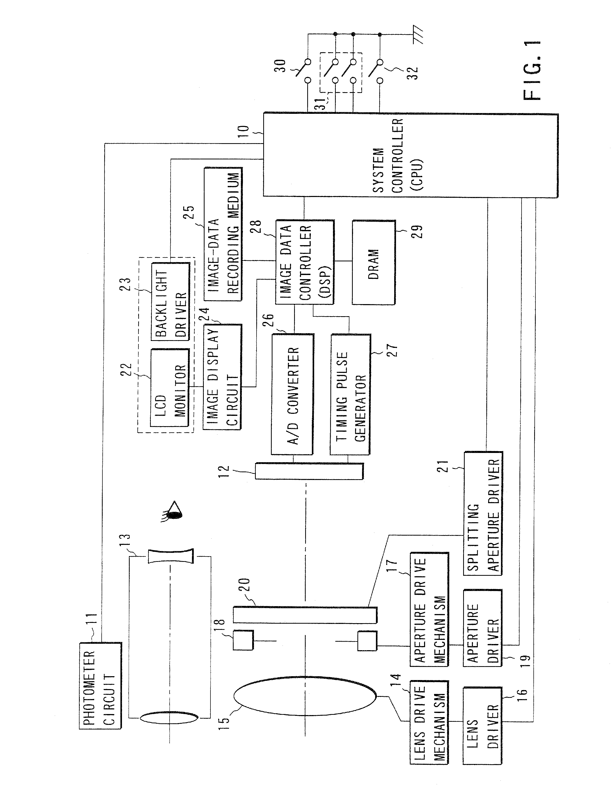
[0050]FIG. 1 is a block structural diagram of an electronic still camera according to a first embodiment of this invention.

[0051] A system controller (hereinafter called “CPU”) 10 performs the general control of the electronic still camera according to this embodiment. A photometer circuit 11 measures the luminance of a subject. The CPU 10 determines the set value of an aperture and the integration time of an imaging device (imaging section) 12 based on the luminance information from the photometer circuit 11. A finder 13 is used to check an imaging area. A lens drive mechanism 14 has an actuator such as a motor and converts the drive force of this actuator to the motion of an imaging lens 15 on the optical axis. Power is supplied to the actuator from a lens driver 16. The CPU 10 can arbitrarily set the position of the imaging lens 15 by controlling the lens driver 16. An aperture drive mechanism 17 has an actuator such as a step motor and drives blades which constitutes an apertur...

second embodiment

[0074]FIG. 6 is a block structural diagram of a camera according to the second embodiment of this invention. The electronic still camera according to the above-described first embodiment is equipped with the finder optical system and the imaging optical system independent of each other. According to the second embodiment, however, this invention is adapted to an electronic still camera of a single-lens reflex type. For the same components as those of the first embodiment, their descriptions will not be repeated.

[0075] When a quick return mirror 37 is down, the subject image is formed on a focusing screen 36 by the imaging lens 15. The image on the focusing screen 36 is guided to an eyepiece 38 via a pentaprism 35. A proximity sensor 39 is provided in the vicinity of the eyepiece 38. The proximity sensor 39, for which, for example, a photo reflector or the like can be used, detects if the user's eye is close to the eyepiece 38 (if the user is optically seeing the subject). The outpu...

third embodiment

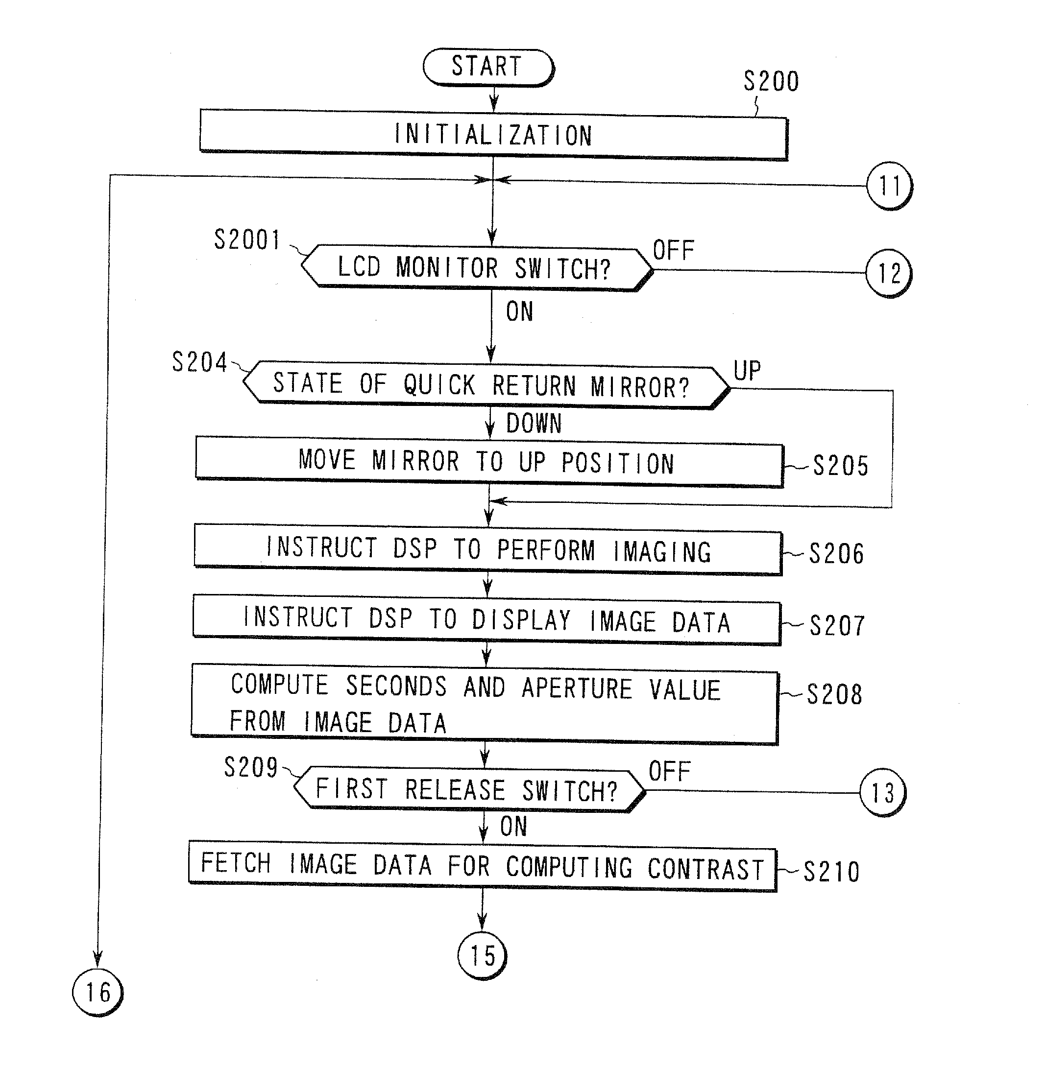
[0089]FIGS. 9A, 9B and 9C are flowcharts for explaining the operation of the CPU 10 according to the third embodiment of this invention. This flow is characterized by removing the proximity sensor for detecting if the finder is in use and the LCD-monitor position detecting switch and providing an LCD monitor switch 100 as shown in FIG. 10 instead.

[0090] The following will discuss only what differs from the flowcharts in FIGS. 8A, 8B and 8C. After initialization is carried out in step S200, the flow goes to step S2001 to determine if the LCD monitor switch 100 is on. If the LCD monitor switch 100 is on, the status of the quick return mirror is then determined in step S204. If the quick return mirror is at the down position, the mirror is driven to the up position and a through screen is displayed on the LCD monitor (step S205). In macro photographing, the user can take a picture while viewing the subject on the LCD monitor in this state. If it is determined in step S2001 that the LC...


PUM


Abstract

An electronic still camera includes a finder optical system for viewing a subject image. An imaging section obtains the subject image. A display section displays the subject image based on image data associated with the subject image obtained by the imaging section. A mode selecting section selects either a first mode in which the electronic still camera performs imaging operation using the imaging section while a user views the subject image through the finder optical system or a second mode in which the electronic still camera performs imaging operation using the imaging section while the user views the subject image on the display section. A first focus detection circuit performs a first focus detecting operation when the first mode is selected by the mode selecting section. A second focus detection circuit performs a second focus detecting operation when the second mode is selected by the mode selecting section.

Description

CROSS-REFERENCE TO RELATED APPLICATIONS [0001] The present application is a Divisional Application of U.S. application Ser. No. 11 / 073,100 filed Mar. 3, 2005 which is a Divisional Application of U.S. application Ser. No. 09 / 570,597 now U.S. Pat. No. 6,882,369, which is based upon and claims the benefit of priority from the prior Japanese Patent Application No. 11-138906, filed May 19, 1999, the entire contents of which are incorporated herein by reference.BACKGROUND OF THE INVENTION [0002] The present invention relates to an electronic still camera. [0003] Electronic still cameras often employ contrast auto focus (AF) using an imaging device. While contrast AF does not require a special optical system or sensor, it suffers a slow operation because it seeks a focus point while driving the lens. [0004] Jpn. Pat. Appln. KOKAI Publication No. 9-181954 and Jpn. Pat. Appln. KOKAI Publication No. 10-319310 disclose the technique that acquires image data by alternately moving apertures for ...

Claims


Application Information

Patent Timeline
Patent Type & Authority Applications(United States)
IPC IPC(8): H04N5/232G02B7/28G02B7/34G02B7/36G03B13/36G03B19/02H04N5/228
CPCH04N5/23293H04N5/23212H04N23/531H04N23/672H04N23/673H04N23/65H04N23/63
Inventor ITO, JUNICHI
Owner OLYMPUS CORP
Why Eureka
Try Eureka