Tape measure having digital output

Inactive Publication Date: 2008-03-27
HU A TE
View PDF16 Cites 10 Cited by
  • Summary
  • Abstract
  • Description
  • Claims
  • Application Information

AI Technical Summary

Benefits of technology

[0009]The primary objective of the present invention is to provide a tape measure including a digital output for precisely converting and showi

Problems solved by technology

It will be difficult for the user to precisely read and take t

Method used


Image

  • Tape measure having digital output
  • Tape measure having digital output
  • Tape measure having digital output

Examples


Example

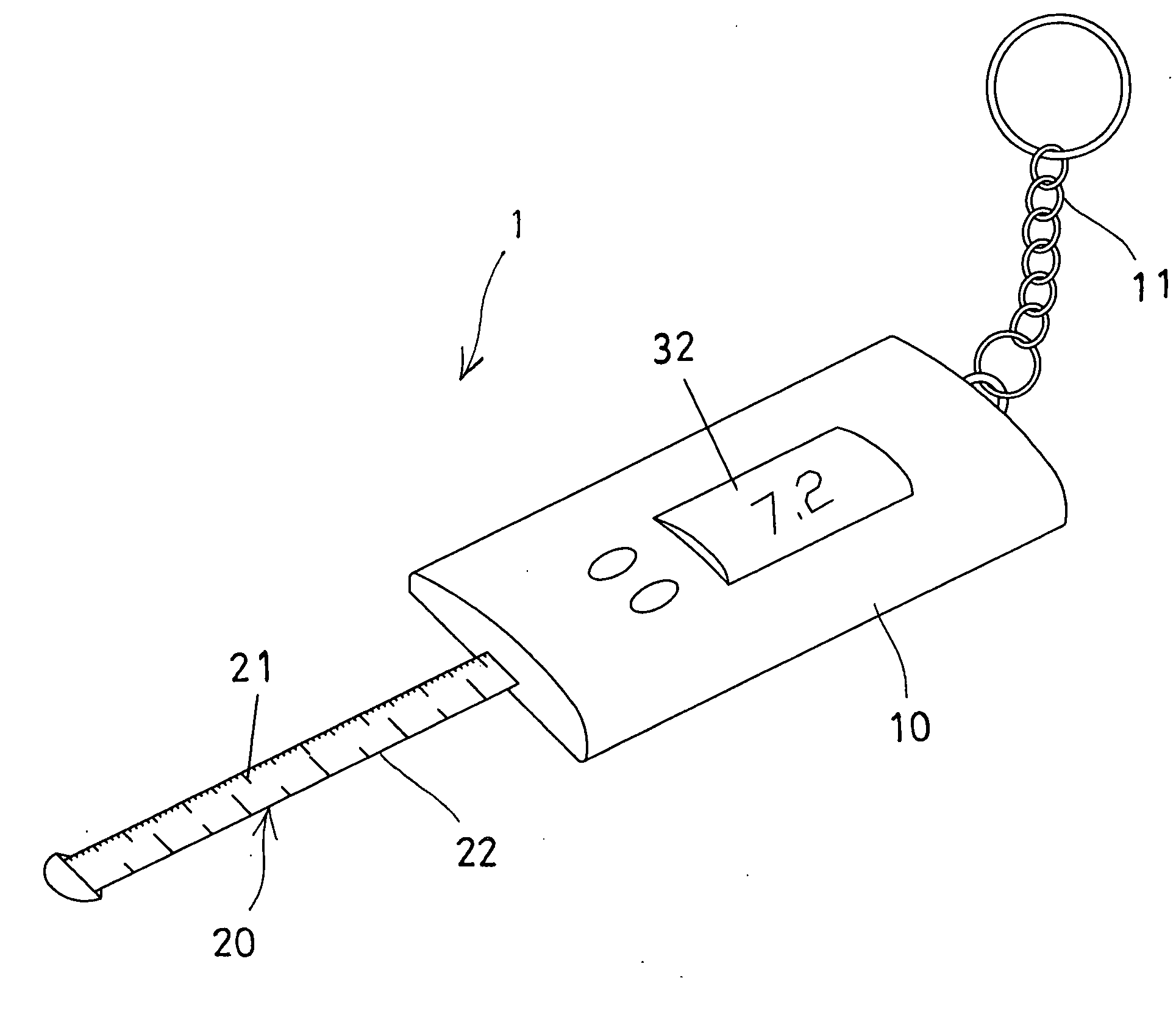
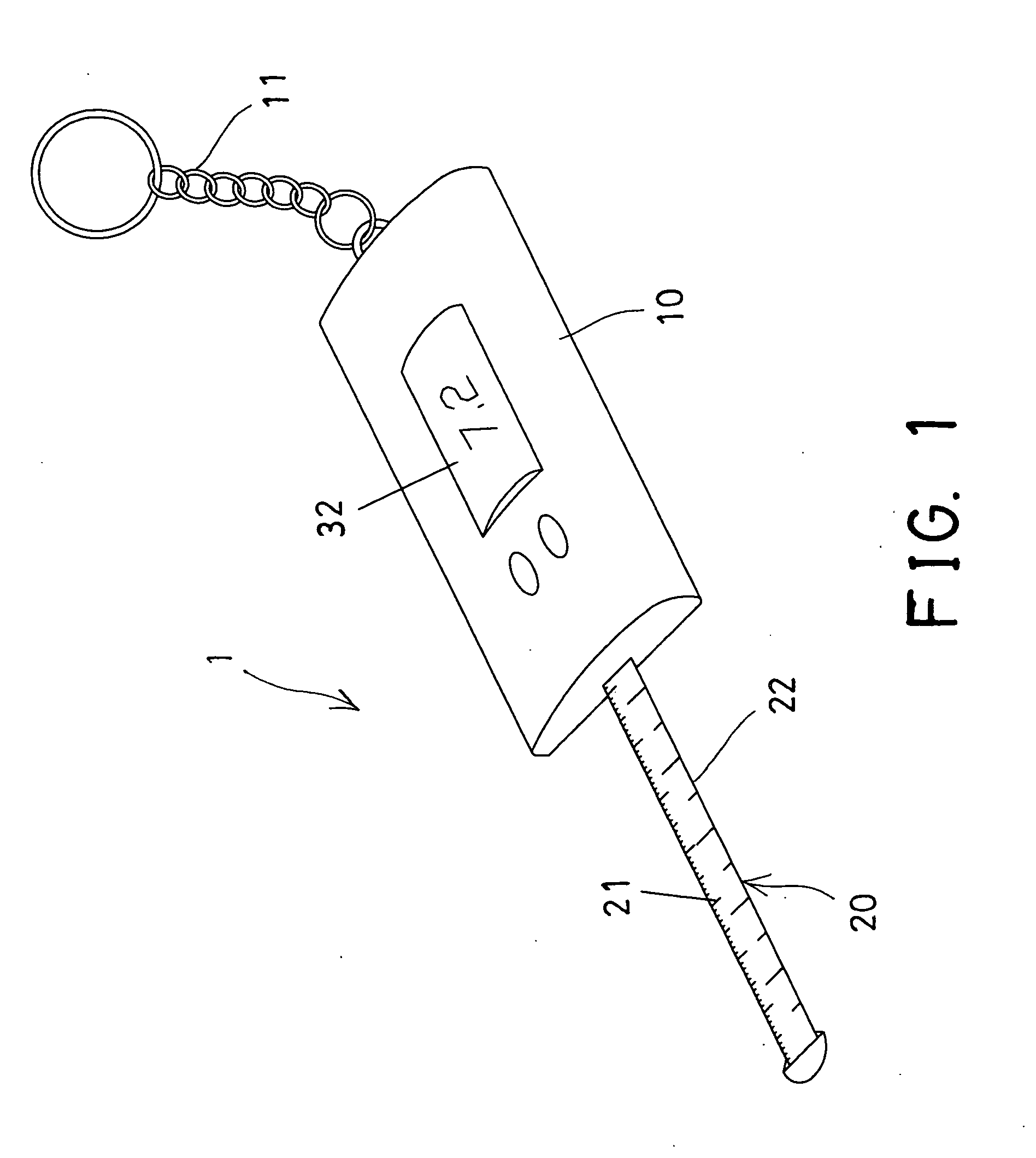
[0018]Referring to the drawings, and initially to FIGS. 1 and 2, a tape measure 1 in accordance with the present invention comprises an outer casing or housing 10, and a measuring tape 20 to be received as a coil within the housing 10 and to be pulled and moved out of the outer housing 10 by the users or workers for tape measuring purposes. The measuring tape 20 may include a metric indicia or graduation 21 and / or a British indicia or graduation 22 provided on either or both sides of its surface. The above-described structure of the tape measure 1 is typical and will not be described in further details.

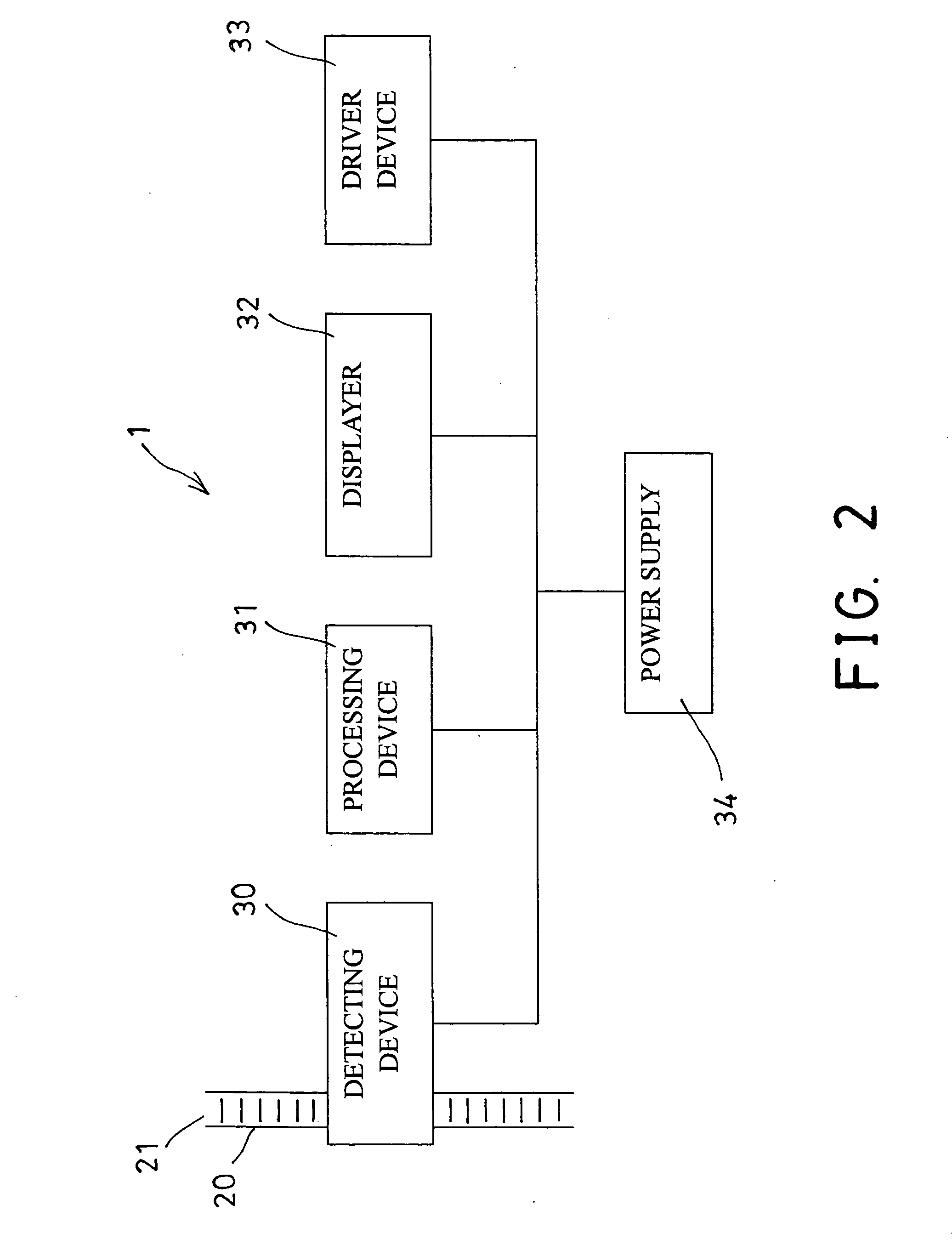
[0019]As shown in FIG. 2, the tape measure 1 further includes a detecting device 30 disposed in the housing 10 and coupled to the measuring tape 20 for detecting or measuring the movement or the moving distance of the measuring tape 20 relative to the housing 10 and / or the detecting device 30. The detecting device 30 may be selected from an infrared detecting device 30, a photo-sensit...


PUM


Abstract

A tape measure includes a measuring tape for measuring purposes, a detecting device coupled to the measuring tape for measuring a moving distance of the measuring tape relative to the detecting device, a processing device coupled to the detecting device for calculating a value detected by the detecting device into a digital output, a displayer coupled to the processing device for displaying the digital output corresponding to the moving distance of the measuring tape relative to the detecting device, and a driver device coupled to the displayer for actuating the displayer to display the digital output and for allowing the work pieces or objects to be easily and quickly measured by the users.

Description

BACKGROUND OF THE INVENTION[0001]1. Field of the Invention[0002]The present invention relates to a tape measure, and more particularly to a tape measure including a digital output for precisely converting and showing the detected distance into a digital value and for allowing the user to easily and quickly measure the work pieces or objects to be measured.[0003]2. Description of the Prior Art[0004]Typical tape measures comprise a measuring tape made of such as a metal strip and having suitable indicia on one or both sides of its surface and having a transverse curvature for giving the measuring tape a tendency to expand outwardly and to hold a straight line position when drawn outwardly from its casing.[0005]For example, U.S. Pat. No. 5,040,256 to Mills, and U.S. Pat. No. 5,119,521 to Clontz disclose two of the typical tape measures each also comprising a measuring tape received as a coil within an outer housing or casing and movable out of the outer housing or casing for tape measu...

Claims


Application Information

Patent Timeline
IPC IPC(8): G01B3/10
CPCG01B3/04G01B3/1084G01B2003/1094G01B2003/1046G01B2003/1048G01B3/11G01B3/1048G01B3/1094G01B3/1046
Inventor HU, A TE
Owner HU A TE
Why Eureka
Try Eureka