
Composite cement retainer

a cement retainer and cement technology, applied in the direction of fluid removal, sealing/packing, borehole/well accessories, etc., can solve the problems of long milling operation time, high cost, and inability to remove the drilling operation in tim

Inactive Publication Date: 2008-03-27
NINE DOWNHOLE TECHNOLOLGIES LLC
View PDF62 Cites 42 Cited by
  • Summary
  • Abstract
  • Description
  • Claims
  • Application Information

AI Technical Summary

Benefits of technology

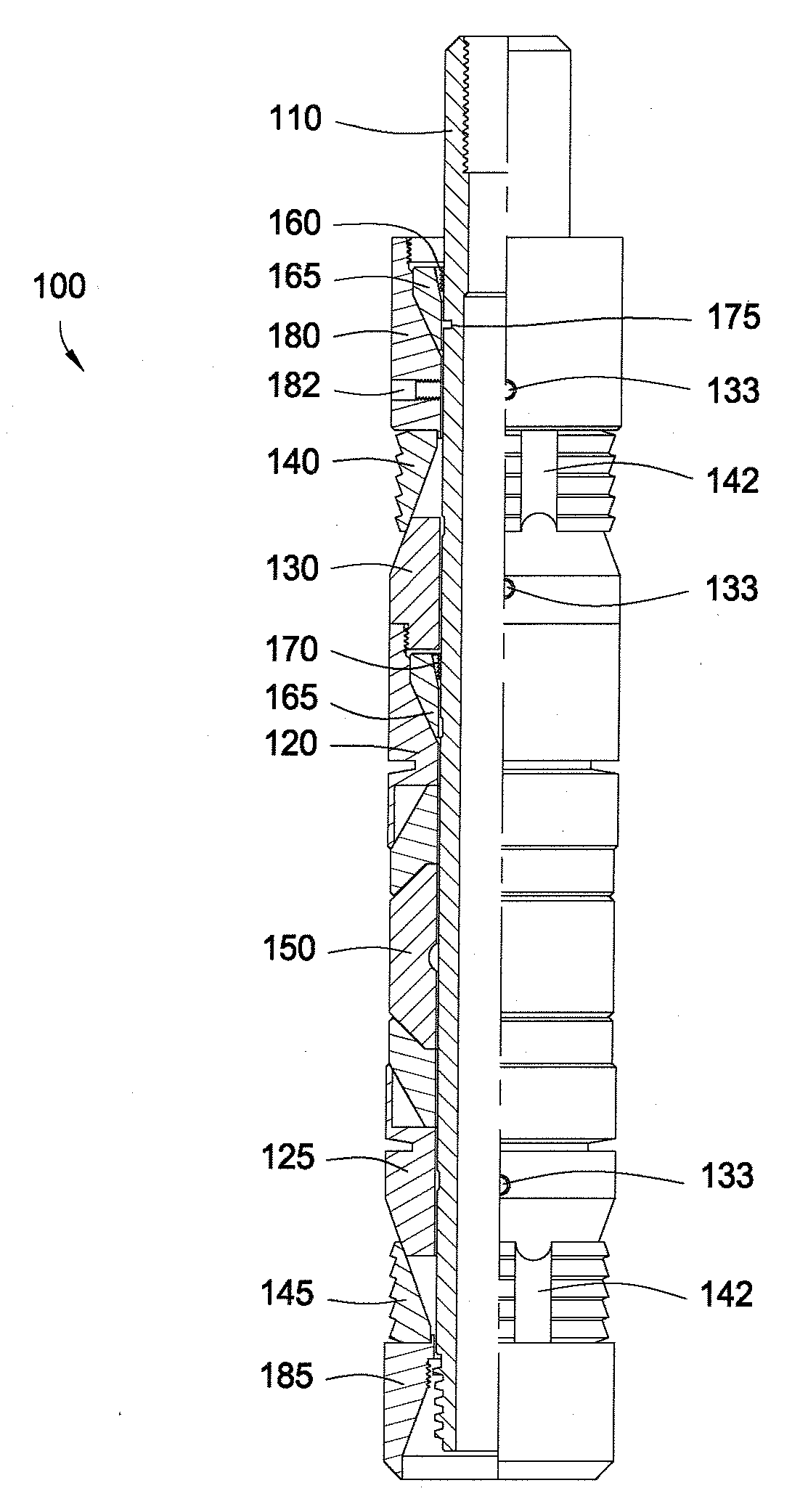
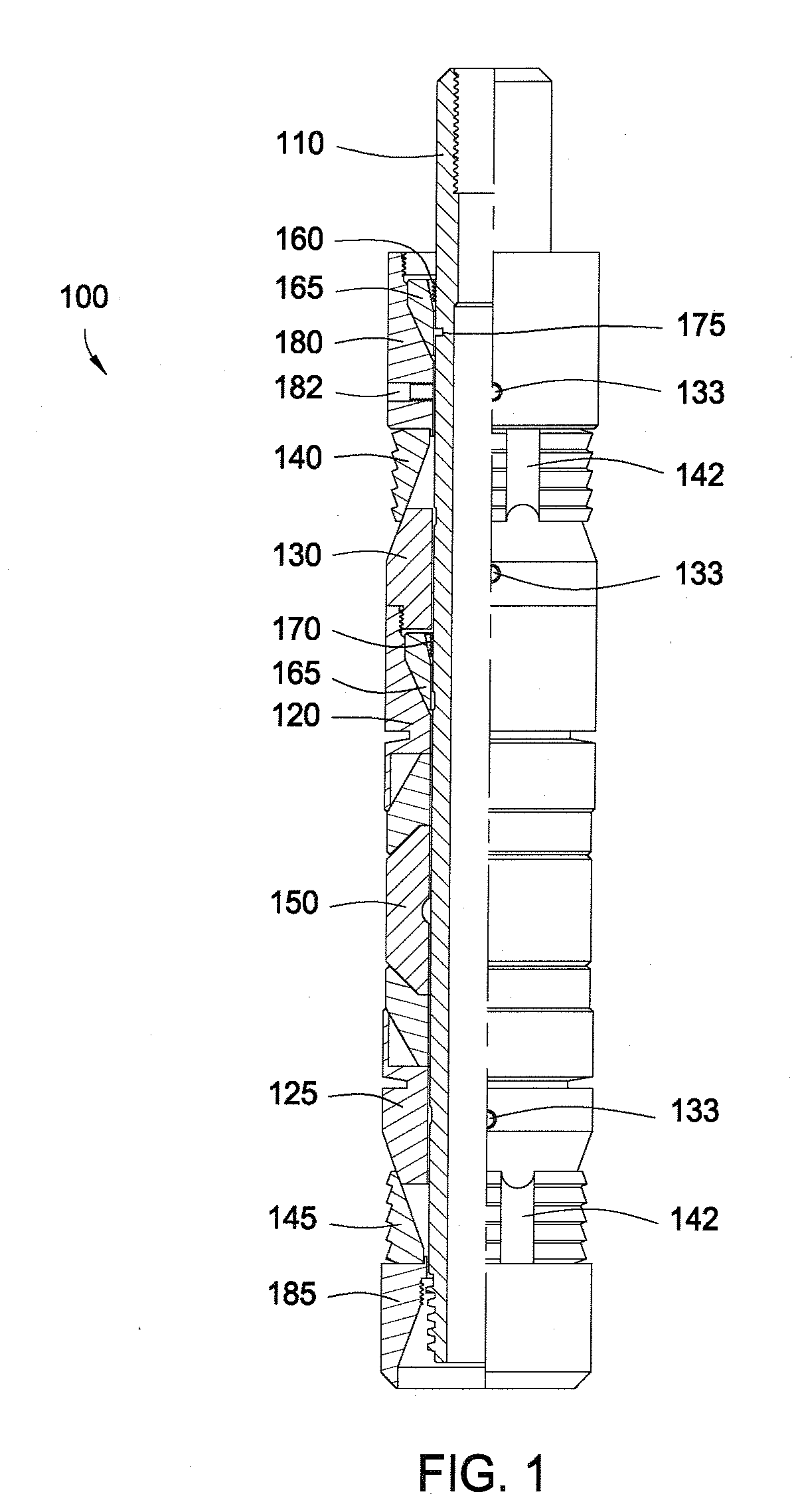
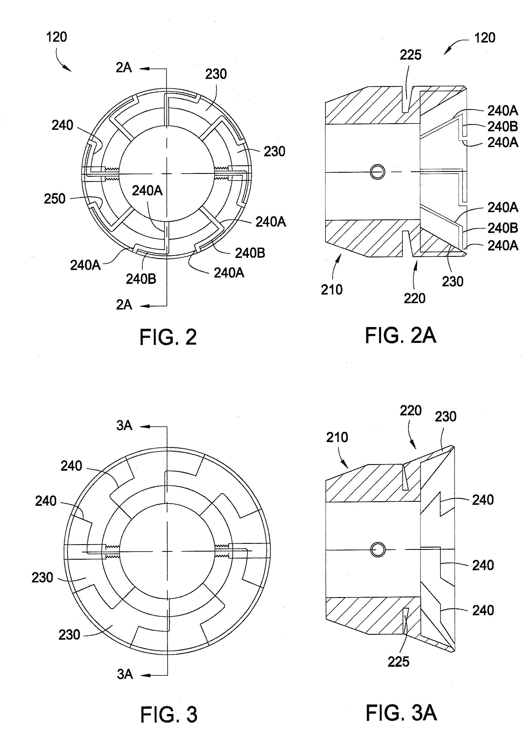
[0013]A non-metallic sealing system, tool, cement retainer, and method for using the same are provided. In at least one specific embodiment, the plug includes a body and an element system disposed about the body. The plug further includes a first and second back-up ring member having two or more tapered wedges. The tapered wedges are at least partially separated by two or more converging grooves. First and second cones are disposed adjacent the first and second back-up ring members.
[0014]In at least one other specific embodiment, the plug includes a body; an element system disposed about a first end of the body; a first and second back-up ring member having two or more tapered wedges, wherein the tapered wedges are at least partially separated by two or more converging grooves; a first and second cone disposed adjacent the first and second back-up ring members; a collet valve assembly disposed about a second end of the body. The collet valve assembly includes a housing having a fir

Problems solved by technology

The valves and cement in the casing are typically destroyed with a rotating milling or drilling device.
The more metal parts making up the valves, the longer the milling operation takes.
Depending on the types (i.e. hardness) of the metals in the valves, the drilling removal operation can be extremely timely and expensive for a well operator.
Such body and gripping members are typically made of metallic components that difficult to drill or mill.

Method used


Image

  • Composite cement retainer
  • Composite cement retainer
  • Composite cement retainer

Examples


Embodiment Construction

[0030]A detailed description will now be provided. Each of the appended claims defines a separate invention, which for infringement purposes is recognized as including equivalents to the various elements or limitations specified in the claims. Depending on the context, all references below to the “invention” can in some cases refer to certain specific embodiments only. In other cases it will be recognized that references to the “invention” will refer to subject matter recited in one or more, but not necessarily all, of the claims. Each of the inventions will now be described in greater detail below, including specific embodiments, versions and examples, but the inventions are not limited to these embodiments, versions or examples, which are included to enable a person having ordinary skill in the art to make and use the inventions, when the information in this patent is combined with available information and technology.

[0031]As used herein, the terms “connect”, “connection”, “conne...


PUM


Abstract

A downhole plug is provided. In one or more embodiments, the plug includes a body and an element system disposed about the body. The plug further includes a first and second back-up ring member having two or more tapered wedges. The tapered wedges are at least partially separated by two or more converging grooves. First and second cones are disposed adjacent the first and second back-up ring members.

Description

REFERENCE TO RELATED APPLICATIONS[0001]This application claims benefit of U.S. Provisional Patent Application having Ser. No. 60 / 846,984, filed on Sep. 25, 2006, which is incorporated by reference herein.BACKGROUND OF THE INVENTION[0002]1. Field of the Invention[0003]Embodiments of the present invention generally relate to a composite downhole tool for hydrocarbon production and method for using same. More particularly, embodiments of the present invention generally relate to a composite cement retainer and method for using same.[0004]2. Description of the Related Art[0005]A wellbore is drilled to some depth below the surface to recover hydrocarbons from subterranean formations. The wellbore can be lined with tubulars or casing to strengthen the walls of the borehole. To further strengthen the walls of the borehole, the annular area formed between the casing and the borehole can be filled with cement to permanently set the casing in the wellbore.[0006]Cement is typically pumped from...

Claims


Application Information

Patent Timeline
IPC IPC(8): E21B33/129
CPCE21B33/134E21B33/1294
Inventor FRAZIER, W. LYNN
Owner NINE DOWNHOLE TECHNOLOLGIES LLC
Learn More