
Liquid receiving device and liquid ejecting apparatus

a liquid receiving device and liquid ejector technology, applied in the direction of printing, other printing apparatus, etc., can solve the problems of unsatisfactory settlement, difficult for such a solvent-applied ink absorber to successfully absorb a large amount of waste ink drops, etc., to facilitate the formation of an initial ink flow channel, smooth and efficient flow, and efficient drainage

Inactive Publication Date: 2008-03-27
SEIKO EPSON CORP
View PDF9 Cites 3 Cited by
  • Summary
  • Abstract
  • Description
  • Claims
  • Application Information

AI Technical Summary

Benefits of technology

[0007]An advantage of some aspects of the invention is to provide a liquid receiving device that is capable of ensuring a smooth and efficient flow of discharged liquid, which has been caught by a liquid receiving portion thereof, into a liquid drainage portion thereof, and further ensuring a smooth and efficient drainage of the liquid from the liquid drainage portion thereof. In addition thereto, advantageously, the invention further provides a liquid ejecting apparatus that is provided with such a liquid receiving device.
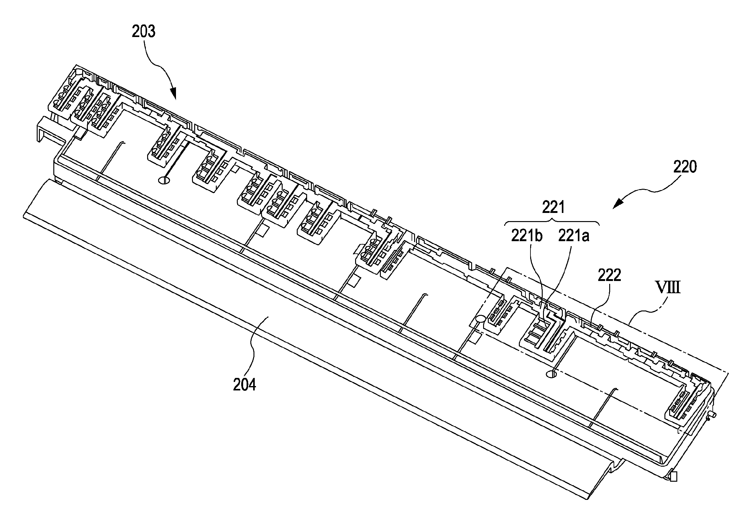
[0008]In order to address the above-identified problem without any limitation thereto, the invention provides, as a first aspect thereof, a liquid receiving device including: a liquid receiving portion that receives discharged liquid; and a liquid drain portion that drains the liquid that has flowed from the liquid receiving portion into the liquid drain portion; wherein the liquid receiving portion has an arrangement area where a first liquid absorber that absorbs the discharged liquid is arranged, the arrangement area having a liquid guiding structure that guides the liquid absorbed by the first liquid absorber to the liquid drain portion; and the liquid drain portion has a second liquid absorber that absorbs the liquid that has flowed from the liquid guiding structure, the liquid drain portion having an absorber compression portion that compresses at least a part of the second liquid absorber. In such a configuration, liquid travels through the liquid guiding structure, which facilitates the formation of an initial ink flow channel. In addition thereto, since liquid flows in / along the liquid guiding structure, it is possible to prevent any undesirable spread of the liquid. Therefore, the invention makes it possible to improve the liquid-guiding capability of the liquid receiving portion. Since the absorber compression portion increases the density of the liquid absorber, it is possible to improve the liquid-sucking capability of the liquid drain portion due to a capillary phenomenon; and in addition, it is further possible to reduce liquid retention capability thereof so as to facilitate the drainage of the spilt liquid due to its “water head” (stress) value.
[0009]In the configuration of the liquid receiving device according to the first aspect of the invention described above, it is preferable that the liquid guiding structure is configured as a groove or a ridgeline. With such a configuration, it is possible to effectively canalize / guide liquid so that it flows inside the groove or along the ridgeline. In the configuration of the liquid receiving device according to the first aspect of the invention described above, it is preferable that the absorber compression portion can press at least the center of the liquid absorber or in the neighborhood thereof. With such a configuration, it is possible to compress the liquid absorber in a substantially uniform manner. Therefore, it is possible to improve the liquid absorption efficiency and the liquid drainage efficiency of the liquid absorber.
[0010]In order to address the above-identified problem without any limitation thereto, the invention provides, as a second aspect thereof, a liquid ejecting apparatus that ejects liquid onto a liquid ejection target medium, the liquid ejecting apparatus being provided with the liquid receiving device having the configuration described above. With such a configuration, it is possible to provide a liquid ejecting apparatus that can offer the above working effects and advantages for any liquid that falls outside the edges of a liquid ejection target medium at the time of marginless ejecting. In addition thereto, the invention makes it possible to provide a liquid ejecting apparatus that can improve liquid collection efficiency.

Problems solved by technology

Therefore, there is a possibility that the drained / discarded ink dries on the surface of the ink absorber to cause undesirable settlement thereon.
Accordingly, it is difficult even for such a solvent-applied ink absorber to successfully absorb a large amount of waste ink drops.

Method used


Image

  • Liquid receiving device and liquid ejecting apparatus
  • Liquid receiving device and liquid ejecting apparatus
  • Liquid receiving device and liquid ejecting apparatus

Examples


Embodiment Construction

[0021]With reference to the accompanying drawings, an exemplary embodiment of the invention is explained below. Although the invention is described below while explaining an exemplary embodiment thereof, the specific embodiment described below is not intended to limit the scope of the invention recited in the appended claims and thus should in no case be understood to restrict thereof; nor is it always necessary to encompass all of combination(s) of features discussed in the following embodiment as means for solving the problem identified by the invention.

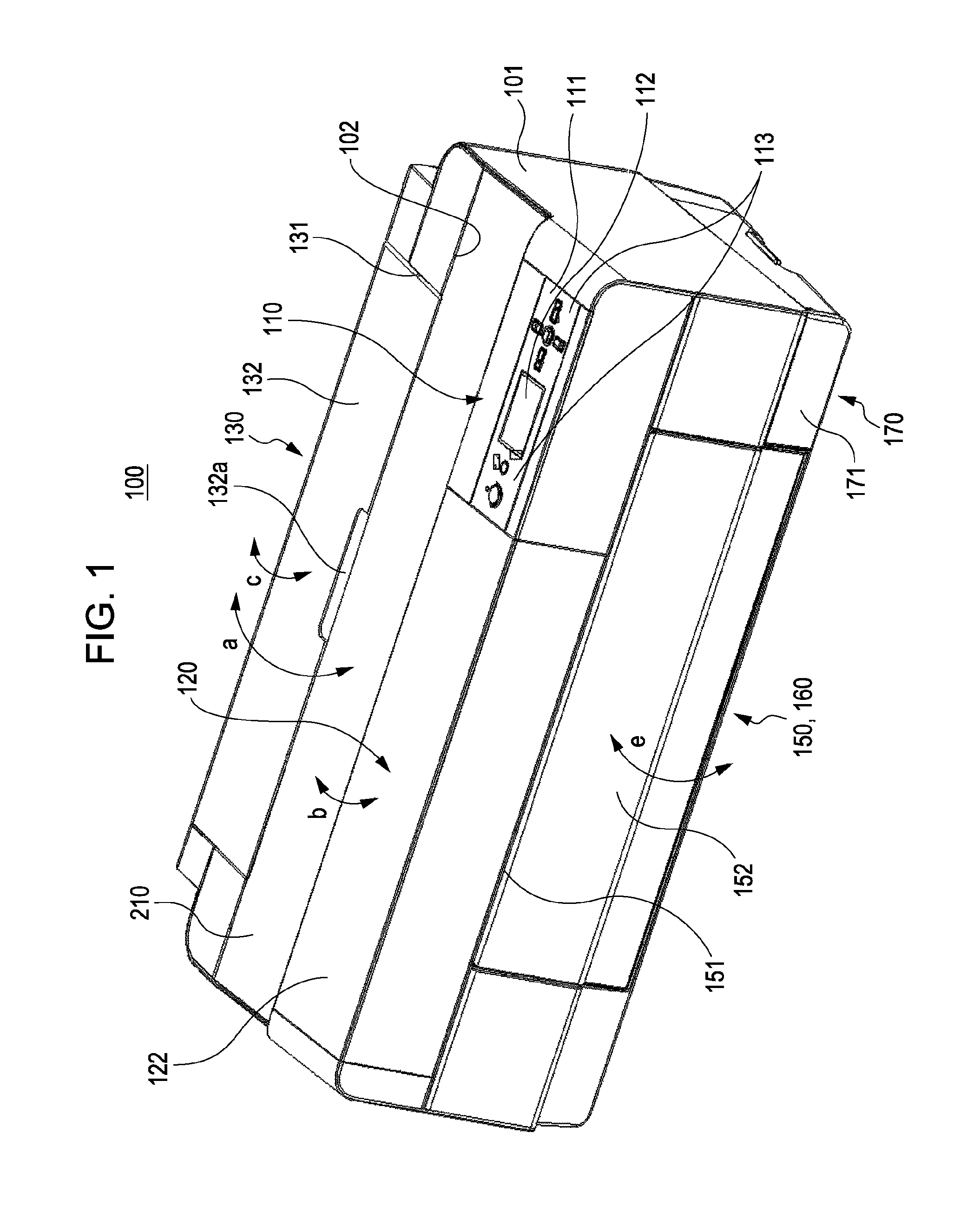
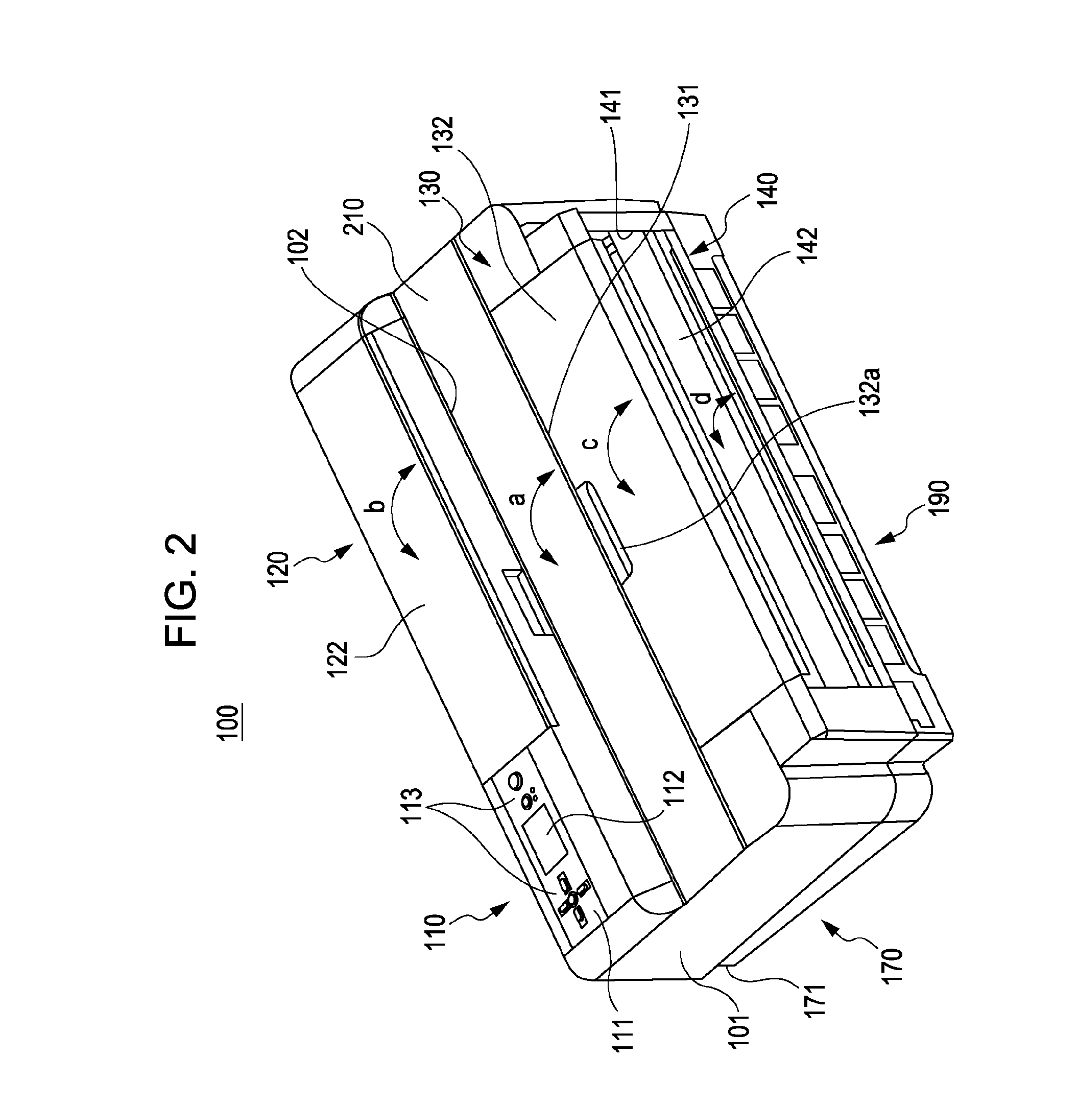
[0022]FIG. 1 is a front perspective view that schematically illustrates an example of the general appearance of an ink-jet printer, which is taken as an example of various kinds of liquid ejecting apparatuses according to an embodiment of the invention. FIG. 2 is a rear perspective view that schematically illustrates an example of the general appearance of the ink-jet printer illustrated in FIG. 1. FIG. 3 is another front perspecti...


PUM


Abstract

The invention provides a liquid receiving device that includes: a liquid receiving portion that receives discharged liquid; and a liquid drain portion that drains the liquid that has flowed from the liquid receiving portion into the liquid drain portion; wherein the liquid receiving portion has an arrangement area where a first liquid absorber that absorbs the discharged liquid is arranged, the arrangement area having a liquid guiding structure that guides the liquid absorbed by the first liquid absorber to the liquid drain portion; and the liquid drain portion has a second liquid absorber that absorbs the liquid that has flowed from the liquid guiding structure, the liquid drain portion having an absorber compression portion that compresses at least a part of the second liquid absorber.

Description

BACKGROUND[0001]1. Technical Field[0002]The present invention relates to a liquid receiving device that receives discharged liquid and then drains thereof. The invention further relates to a liquid ejecting apparatus that is provided with such a liquid receiving device.[0003]2. Related Art[0004]Some of ink-jet printers of related art can perform “marginless” printing. Such an ink-jet printer, which is an example of various kinds of liquid ejecting apparatuses, is capable of recording ink dots on the entire surface of a sheet of paper, which is an example of various kinds of recording target media, without leaving any paper margin. A platen built in such an ink-jet printer has an ink-receiving portion (i.e., ink catcher), ink-guiding grooves, ink drain paths, and an ink reservoir portion formed therein. The platen functions to support a sheet of paper and to determine its position so that a recording head can perform printing thereon. Any ink drops that have missed the edge portions ...

Claims


Application Information

Patent Timeline
IPC IPC(8): B41J2/165
CPCB41J2/16523B41J2002/1742B41J11/0065B41J2/1742
Inventor SUMII, ATSUSHIKAGAMI, KAZUYUKIOZAKI, KAZUMA
Owner SEIKO EPSON CORP
Learn More