Apparatus and a system for remote control and a method thereof

a remote control and apparatus technology, applied in the field of apparatus and a system for remote control and a method thereof, can solve the problems of increasing the number of required remote control apparatuses, the inability to install routers or firewalls between, and the increase of the introduction cost of a remote control apparatus along with the increase of sub networks

Inactive Publication Date: 2008-04-03
NEC CORP
View PDF4 Cites 28 Cited by
  • Summary
  • Abstract
  • Description
  • Claims
  • Application Information

AI Technical Summary

Problems solved by technology

1. A wake up packet is a broadcast packet transmitted from a remote control apparatus which generates a wake up packet to a power-on target device. However, since a broadcast packet can not pass through a router and a firewall, a router or a firewall can not be installed between a remote control apparatus and a power-on target device. That is, a remote control apparatus needs to be installed in each network unit which is divided by a router or a firewall.
2. With the increase in size of a corporate network, sub networks which exist in a corporate network are increasing in number. For this reason, power-on target devices which use a wake up packet are separately installed in many sub networks. Accordingly, the number of required remote control apparatuses is increasing along with the increase of sub networks. As a result, in a remote control system mentioned above, an introduction cost of a remote control apparatus increases along with the increase of sub networks.
3. In a remote power-on system using a wake up packet, a remote control apparatus exists for each sub network. Thus, an operator needs to store information about a power-on target device managed by each remote control apparatus into each remote control apparatus. When a power-on target device is moved to another network, an operator has to register again information thereof to each remote control apparatus. Further, it is necessary for a user to acquire, from the operator, the latest information of a remote control apparatus on a sub network on which a power-on target device is installed and to store the information into a portable computer. A user needs to always keep a content of a portable computer correct so that a user can correctly designates a remote control apparatus which manages a power-on target device by using a correct destination address for an instruction packet. As a result, in the remote power-on system above-mentioned, a maintenance / operation cost of a remote control apparatus, after introducing becomes high.
4. Also, a wake up packet cannot pass through a router and a firewall. For this reason, in a remote power-on system of related arts, a remote control apparatus and a power-on target device have to be installed in the same network. Also, in the remote power-on system of related arts, a device in a firewall cannot be activated by a remote control apparatus located out of the firewall even if a remote control apparatus is installed outside of a firewall of a company network.
5. Accordingly, even if an administrator of a network wants to provide a convenient system for users, but it is difficult to introduce a remote power-on system using a WOL technology in view of difficulties in operations and management.
6. In the reference 2 mentioned in the background art, a WOL apparatus is located on a sub network to which a device of power-on target belongs. Accordingly, it is necessary for a user to designate a WOL apparatus installed for each sub network and to transmit an activation instruction packet. The reference 2 does not handle the above-mentioned difficulties.

Method used


Image

  • Apparatus and a system for remote control and a method thereof
  • Apparatus and a system for remote control and a method thereof
  • Apparatus and a system for remote control and a method thereof

Examples


Embodiment Construction

[0045]Exemplary embodiments of the present invention will now be described in detail in accordance with the accompanying drawings.

[0046]FIG. 3 shows a first exemplary embodiment of a remote control system of the present invention. FIG. 3 shows an example of a remote control system in which a power supply of a control target (i.e. server) is remotely turned on by a terminal (i.e. portable computer) that is placed far from the control target.

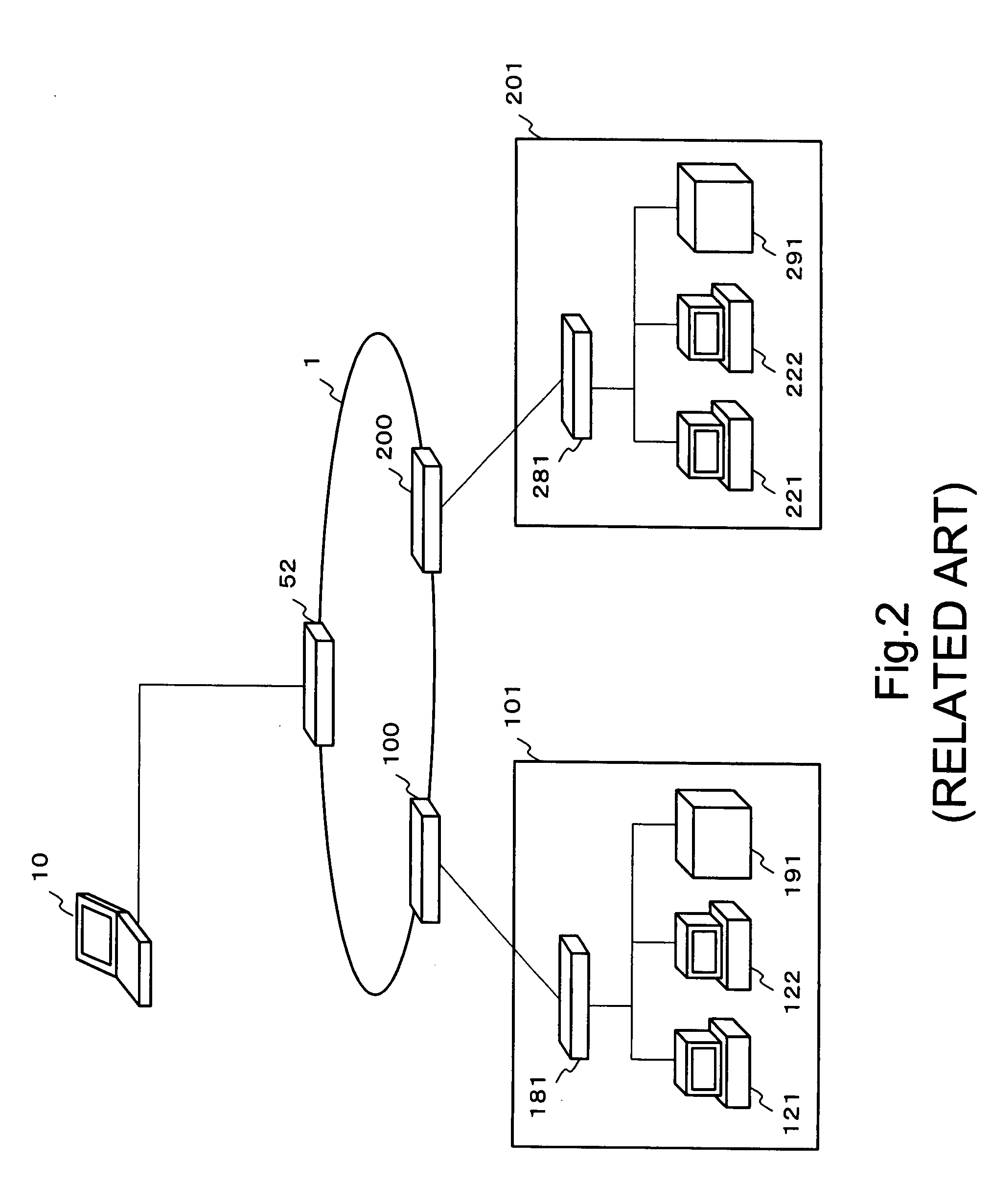
[0047]The remote control system includes a backbone network 1 and sub networks 2, 101 to N01 as shown in FIG. 3.

[0048]The sub network 2 connects with the backbone network 1 via routers 51 and 52. The sub network 101 connects with the backbone network 1 via routers 100 and 111. The sub network 101 accommodates the router 111 and servers 121, 122. The sub network 201 connects with the backbone network 1 via routers 200 and 211. The sub network 201 accommodates the router 211 and servers 221, 222.

[0049]Similarly, a N-th sub network N01 which accommod...


PUM


Abstract

Disclosed is a remote control system which includes a remote control apparatus on a network, a control packet transmitter which is on a sub network and connects with the remote control apparatus via a network interconnecting apparatus, an operation terminal which can connect with the remote control apparatus, and a control target on the sub network of the control packet transmitter. The operation terminal transmits information which includes a control content of the control target to the remote control apparatus. The remote control apparatus includes a table including an address of the control packet transmitter and an address of the control target. The remote control apparatus transmits a control request packet including the acquired address of the control target and control content to the control packet transmitter. The control packet transmitter transmits a control packet including a control content designated by a control request packet to the control target.

Description

INCORPORATION BY REFERENCE[0001]The application is based on Japanese Patent Application No. JP 2006-263732 filed on Sep. 28, 2006, and including a specification, claims, drawings and summary. The disclosure of the above Japanese Patent Application is incorporated herein by reference in its entirety.BACKGROUND OF THE INVENTION[0002]1. Technical Field[0003]The present invention relates to a technology for remotely controlling a control target connected with a network.[0004]2. Background Art[0005]A Wake on LAN (hereinafter described as “WOL”) technology is known as a technology by which a user remotely turns on a power supply of a network device such as a personal computer (PC) and a server. In the technology, a wake up packet is transmitted to a device to which no power is supplied and the device which receives the wake up packet is activated.[0006]Magic Packet technology is known as one of related arts which specifically realize a WOL technology. In the technology, a packet called a ...

Claims


Application Information

Patent Timeline
Patent Type & Authority Applications(United States)
IPC IPC(8): H04L12/56H04L9/32H04L12/46H04L12/70H04M11/00
CPCH04L12/12Y02B60/34H04L63/08H04L63/029Y02D30/50
Inventor SHIMURA, MIKIKOYAMAGUCHI, YASUHIRO
Owner NEC CORP
Why Eureka
Try Eureka