Dust vacuuming abrasive tool

Inactive Publication Date: 2008-04-03
3M INNOVATIVE PROPERTIES CO
View PDF99 Cites 56 Cited by
  • Summary
  • Abstract
  • Description
  • Claims
  • Application Information

AI Technical Summary

Benefits of technology

[0049] Arrangement of perforations 24, 24′ is configured to be contiguous lattice where the centers of three adjacent perforations form an equilateral triangle. The distance between adjacent perforations, which are located at vertices of an equilateral triangle, is not greater than about 1.5 times, and preferably from 0.5 to 1.5 times the diameters of the perforations. If the distance between adjacent perforations is greater than 1.5 times the diameters of the perforations, the perforations of the abrasive sheet material and those of the

Problems solved by technology

This swarf has to be removed otherwise the surface of the abrasive material would become clogged, resulting in reduced abrading efficiency.
When an abrasive material is mounted on the pad, the work of attaching the abrasive material while visually confirming the alignment of the perforations in the pad and in the abrasive material is troublesome.
In the case where the perforations in the abrasive material do not align with the perforations in the pad, the number of perforations in the abrasive surface is effectively reduced, and therefore, sufficient dust vacuuming performance cannot be obtained.
Therefore, when the type of abrasive material is changed, and the alignment of the perforations, or the format of the perforations changes, it also may be necessary to change the back-up pad accordingly, which is time-consuming and inefficient.

Method used


Image

  • Dust vacuuming abrasive tool
  • Dust vacuuming abrasive tool
  • Dust vacuuming abrasive tool

Examples


example 1

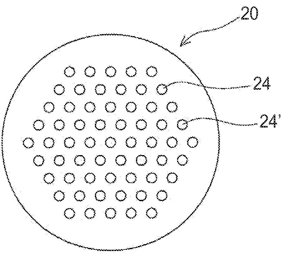
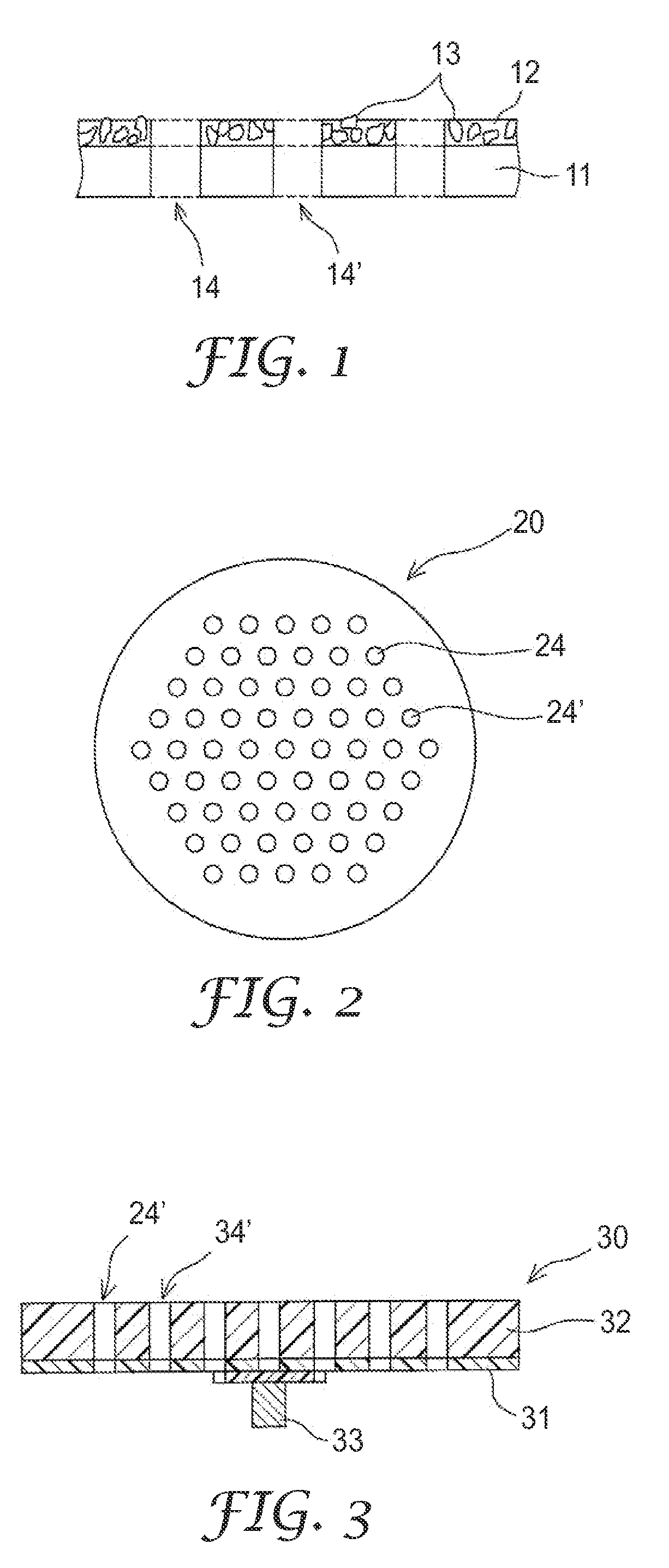
[0072] A nylon pile loop material of a mechanical fastener was attached to the back surface of an abrasive material “Disc Unicut P400” having a diameter of 125 mm, made by Sumitomo 3M Ltd. Perforations were formed in the abrasive material to form an opening structure shown in FIG. 2. Thus, an abrasive sheet material was obtained. The total number of circular perforations was 61, all having a diameter of 5.0 millimeters (mm). The centers of three adjacent perforations form an equilateral triangle of length. The distance between adjacent perforations is 6.8 mm.

[0073] A 10 mm-thick sponge sheet was punched into a circle 125 mm in diameter. A hook material of a mechanical fastener was attached to the supporting surface of the resultant sponge disc and a loop material of the mechanical fastener was attached to the back surface. Perforations were formed in the disc material to form an opening structure shown in FIG. 2. Thus, an intermediate pad was obtained. The 5.5 mm diameter perforati...

example 2

[0081] In the supporting surface and back surface of an intermediate pad prepared in the same manner as in Example 1, channels were formed along lines connecting the perforations in concentric loops. FIG. 9 is a diagram showing the support surface and the back surface of the intermediate pad. The channels were formed by removing the hook element on the supporting surface and the loop element on the back surface with a width of 3 mm. A dust vacuuming abrasive tool was obtained in the same manner as in Example 1, except that this intermediate pad was used, and a sanding test performed. The results are shown in Table 3.

example 3

[0082] In the supporting surface and back surface of an intermediate pad prepared in the same manner as Example 1, channels were formed along lines completely connecting the perforations. FIG. 8 is a diagram showing the support surface and the back surface of the intermediate pad. The channels were formed by removing the hook element on the supporting surface and the loop element on the back surface with a width of 3 mm by a melting (fusion) removing method. A dust vacuuming abrasive tool was obtained in the same manner as in Example 1, except that this intermediate pad was used, and a sanding test performed. The results are shown in Table 3.


PUM


Abstract

The present disclosure is directed to a dust vacuuming abrasive tool comprising an abrasive sheet material having an abrasive surface, a back surface and 20 or more perforations; and a backup pad having a support surface, a back surface and 20 or more perforations, or a plurality of perforations and also having, in the supporting surface. The configuration of the abrasive sheet and back-up pad eliminate the need to align perforations in the abrasive sheet and back-up pad.

Description

CROSS-REFERENCE RELATED APPLICATIONS [0001] This application claims priority from Japanese Patent Application No. 2006-268351, filed on Sep. 29, 2006. TECHNICAL FIELD [0002] The present invention relates to a dust vacuuming abrasive tool having an abrasive sheet material with perforations, and a supporting pad with perforations and a ventilative member, for vacuuming dust during abrading work. BACKGROUND ART [0003] Painting coat, clear coat, putty filler, primer and the like are abraded in automobile repairing work and the like. When painting coat, clear coat, putty filler, primer or the like is abraded, a large amount of abraded dust, or swarf, is created. This swarf has to be removed otherwise the surface of the abrasive material would become clogged, resulting in reduced abrading efficiency. Therefore, conventional dust vacuuming abrasive tools having perforations in an abrasive surface are well known. [0004] Such abrasive tools are generally formed of an abrasive sheet material ...

Claims


Application Information

Patent Timeline
IPC IPC(8): B24D11/00
CPCB24D11/00B24B55/102
Inventor TAKINAMI, SATORUOKA, HITOSHI
Owner 3M INNOVATIVE PROPERTIES CO
Why Eureka
Try Eureka