Vacuum variable capacitor

a variable capacitor and vacuum technology, applied in variable capacitors, capacitors with electrode area variation, air/gas/vacuum dielectric ipc5, etc., can solve the problems of unrivaled power applications, inability to deliver electric power, and destruction, so as to reduce the required motor torque, reduce the required vacuum force, and reduce the effect of vacuum for

Active Publication Date: 2016-03-31
COMET
View PDF1 Cites 3 Cited by
  • Summary
  • Abstract
  • Description
  • Claims
  • Application Information

AI Technical Summary

Benefits of technology

[0031]The fast vacuum variable capacitor described here may for example be configured with the motor located outside the pre-vacuum enclosure, and with the gas in the pre-vacuum enclosure at a pressure of approximately 0.1 bar, for example. A pressure of 0.1 bar diminishes the vacuum force on the bellows by approximately 90% but still provides enough molecules to allow convection cooling so that the motor does not overheat. A better vacuum (a lower pressure) may not allow enough heat to be evacuated towards the outside environment leading to overheating of the motor and failure of the system. Generally, a pressure of between 0.05 bar and 0.5 bar has been found to offer a useful reduction in vacuum force, without the need for extra cooling measures. However, any pressure up to atmospheric pressure may be used, and still offer an improvement.
[0032]In principle, the vacuum force could be reduced to zero by fully evacuating the pre-vacuum chamber. This would reduce the required motor torque for (driving the screw / nut or the magnetic coupling to a very small value. However, the vacuum force provides a useful axial biassing force on the screw-nut drive. This axial biassing force significantly reduces the amount of play in the screw / nut drive, and thereby contributes to the accuracy (resolution) of the capacitor adjustment. The bellows may have an inherent spring-like force, which also has the effect of biasing the screw-nut mechanical interface. However, the bellows may be under compression at one point in its extension range, and in tension in another part of its extension range, so it will exert a positive and a negative biasing force on the drive screw / nut, depending on where in its extension range the bellows happens to be. Thus, it is advantageous to configure the pressure differential across the bellows such that the vacuum force is greater than the maximum bellows spring force acting in a direction opposite to the vacuum force. In other words, the resultant “vacuum force+bellows spring force” should not change orientation even when the bellows go through their neutral position (from being compressed to being extended). Indeed although the bellows force alone would change orientation depending whether it is operated in compression mode or in extension mode, the adding of the (diminished) vacuum force still ensures that the sum of the forces does not change orientation. This can be guaranteed by having the secondary vacuum pressure high enough to at least equalize the maximum amplitude of the bellows spring force of the capacitor. A change of orientation of the resultant force would allow backlash in the screw-nut system or the magnetic coupling resulting in an inferior position control of the capacitor (and associated capacitance and impedance values). In other words, the diminished vacuum force should be determined so that it is still just big enough to compensate any bellows force in an opposite direction (this will depend on the mechanical properties of the bellows used).
[0033]For similar reasons, another advantage of a reduced but not fully compensated vacuum force, is that the capacitor can be positioned and integrated in any orientation into an impedance matching network provided that the reduced vacuum force still at least also compensates the gravitational force which applies on the movable electrode when the bellows axis is not horizontal. A pressure of 0.1 bar was found to be appropriate with typical choices of bellows and electrode mass. However, in other situations a higher or lower pressure may be more effective.

Problems solved by technology

Failing to match the impedance would result in electric power not being delivered to the process, but instead being reflected back into the generator which could lead to its destruction.
Moreover, because of the extremely low dielectric losses, vacuum capacitors allow large currents without generating much heat and consequently are essentially unrivalled for the most demanding power applications.
While there is progress towards more rapid control software, there are physical limitations on the speed with which a mechanical part (the moving electrode) can be moved using a given motor.
One limiting factor on the speed is the motor power required to counter the significant force due to the pressure differential (1 bar) between the inside and the outside of the vacuum tight enclosure.
State of the art vacuum variable capacitors are thus limited in speed primarily by the power of the motor and by the pressure-velocity limit (so-called PV value) of the screw and nut of the drive system used to move the movable electrode of the capacitor.
A high PV value of the application leads to a high contact pressure between the nut and the screw threads of the drive system, negatively affecting the wear of said screw / nut system and resulting in earlier failures (or alternatively requiring regular exchange of screw / nut system).
Prior art capacitors also suffer from significant membrane stresses and bending stresses in the bellows.
Unfortunately, however, one property of stepper motors is that increasing the speed decreases the available torque, which, at very high speeds, results in step loss and inaccuracy.
Obtaining a combination of higher torque and speed is only possible by drastically increasing the size and cost of the motor.
This is not an acceptable option for components integrated into OEM (original equipment manufacturer) impedance matching networks
This reduced rotational friction also results in a significant decrease in the amount of torque required by the motor to drive the shaft.
The reduced vacuum force also leads to a reduction in the wear of the screw-and-nut drive system, thus leading to longer lifetimes of those components.
A better vacuum (a lower pressure) may not allow enough heat to be evacuated towards the outside environment leading to overheating of the motor and failure of the system.
A change of orientation of the resultant force would allow backlash in the screw-nut system or the magnetic coupling resulting in an inferior position control of the capacitor (and associated capacitance and impedance values).

Method used


Image

  • Vacuum variable capacitor
  • Vacuum variable capacitor
  • Vacuum variable capacitor

Examples


second embodiment

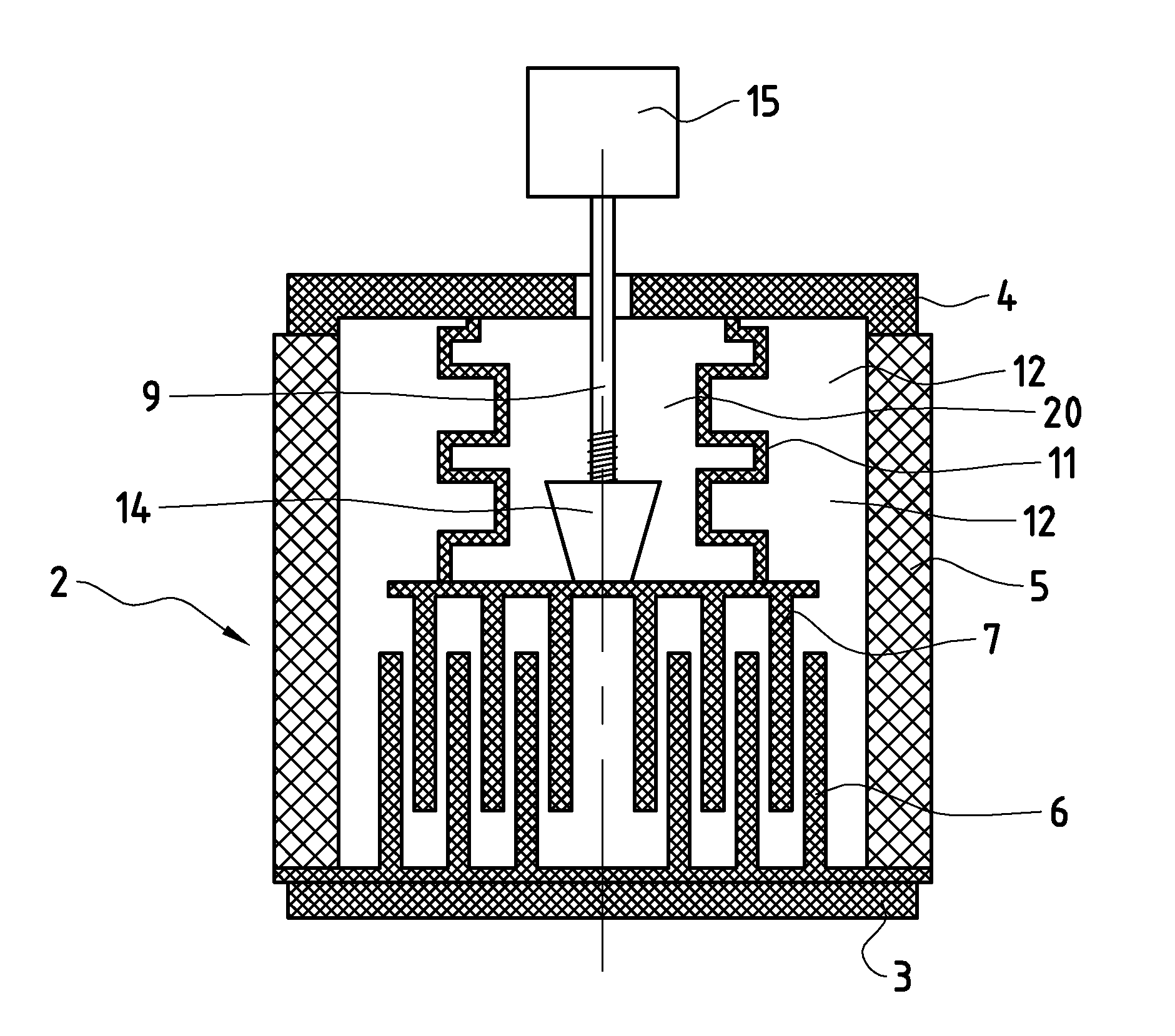
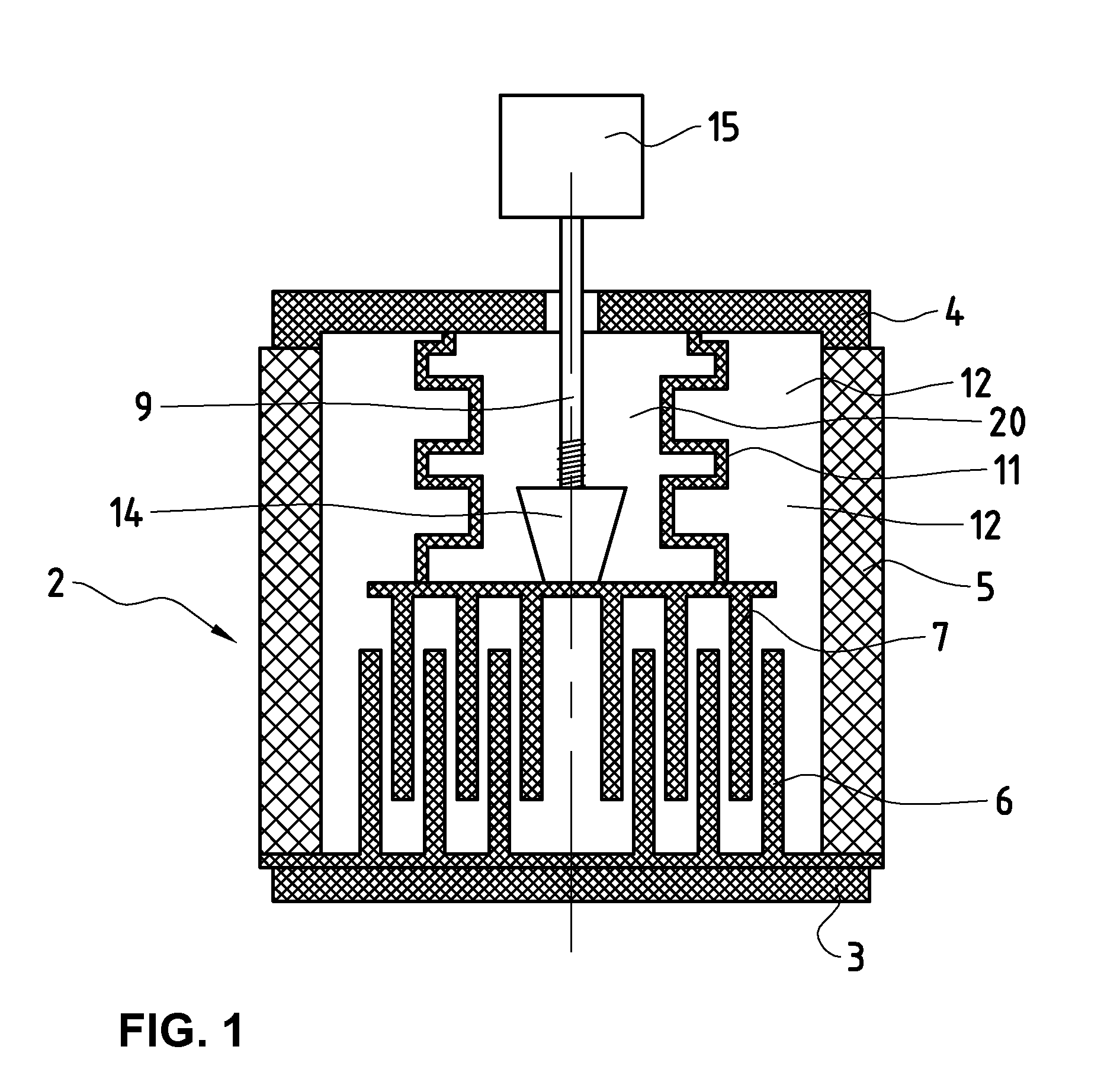
[0049]The collar (4) on the variable side of the vacuum variable capacitor (1) is often referred to as the “variable mounting plate”. It is used to mount the vacuum variable capacitor into an impedance matching network or other system. A different electrode arrangement inside the first vacuum tight enclosure (2) allows to simplify the mounting of the drive system, as will be explained in relation to the invention.

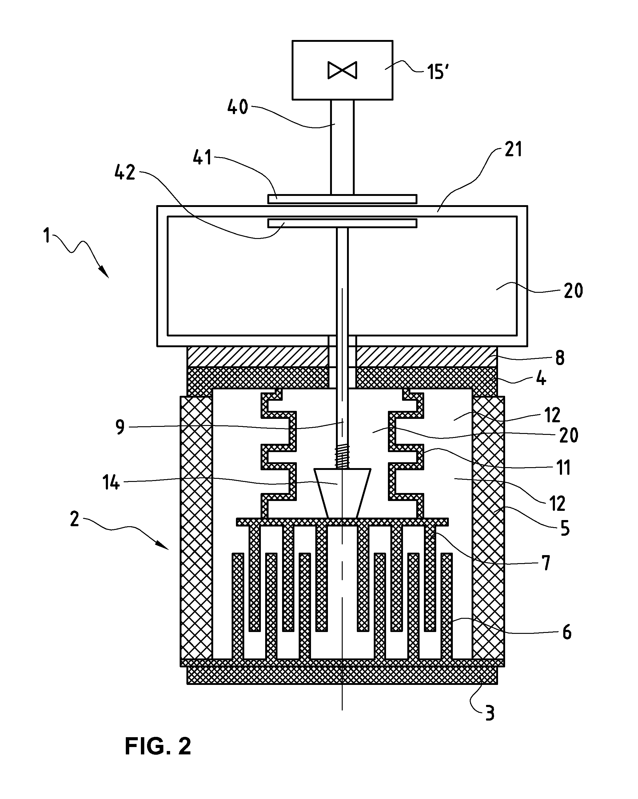
[0050]Coming back to the present embodiment (FIG. 2), let us assume that the pressure in the pre-vacuum enclosure (21) is 0.1 bar for the following discussion about the increase of the lifetime of the vacuum variable capacitor.

[0051]Firstly, the bellows (11) lifetime improves because the pressure differential (ΔP) across the bellows (11) is now reduced by 90%, and this reduction will produce lower membrane stress and lower bending stress of the bellows (11) in extension or compression, thus leading to an extended lifetime. Secondly, the lifetime of the screw (9) and nut (14...

third embodiment

[0064]With this arrangement, it is therefore particularly advantageous to use a linear drive or any other moving means which do not contain a screw and nut. Furthermore with this embodiment, the force necessary to adjust the vacuum variable capacitor is reduced even more than in the previously discussed embodiments, and even higher speeds can be achieved. A linear motor (34) outside the enclosures as drive means and a voice-coil (29) inside the pre-vacuum enclosure (21) as driven means, such as a linear induction or voice-coil type motor, can for example be used to adjust the vacuum variable capacitor of FIG. 4. Furthermore, because the nett vacuum and spring forces on the bellows are effectively reduced to zero, the capacitance adjustment speed does not depend on the pressure in the pre-vacuum enclosure (21). The pressure in the pre-vacuum enclosure (21) could thus be any value, including atmospheric pressure, or a higher-than-atmospheric pressure. Indeed, the vacuum variable capac...

fourth embodiment

[0065]FIG. 5 shows a further example of a vacuum variable capacitor according to the present invention. The general set up of the electrodes (6) and (7), the bellows (11), the lead screw (9) and the nut (14) of the capacitor is realized as shown in FIG. 2. In FIG. 5 the drive means (40) is housed in an enclosure (43) and supported by bearings (44). The magnetic plates (41) and (42) are realised as magnetic blocks in the enclosures (43) and (21) respectively. The magnets are chosen strong enough to guarantee a perfect orientational coupling of the blocks and the respective parts they are attached to in their respective enclosures (43) and (21). Any “slipping” of the two rotationally coupled systems should be avoided during movement and more critically during acceleration and deceleration.

[0066]The arrangement of the motor (15′) outside the vacuum enclosures of the vacuum variable capacitor allows a simple design of the capacitor with several vacuum enclosures and facilitates maintena...


PUM


Abstract

A vacuum variable vapacitor includes a pre-vacuum enclosure for reducing a pressure differential across the bellows, wherein a drive is disposed outside the enclosures of the vacuum variable capacitor. The vacuum force load on the drive system can thereby be reduced, allowing faster movement of the movable electrode, faster capacitance adjustment of the vacuum variable capacitor and longer lifetimes of the device.

Description

BACKGROUND AND SUMMARY[0001]The present invention relates to the field of vacuum variable capacitors.[0002]Vacuum variable capacitors are useful for example in impedance matching networks in which the impedance of a time-dependent high-frequency load can be matched with that of a generator by adjusting one or more vacuum variable capacitors. The capacitance of such capacitors can be controllably adjusted by moving one electrode, or set of electrodes, with respect to the other, and the use of vacuum as the dielectric medium allows their use in high power applications, for example operating at voltages in the kV range or several tens of kV voltages, carrying currents up to several hundred amppere, and at frequencies as low as 200 kHz or as high as 200MHz. Such capacitors can be used as the tuning element in high-power impedance matching networks and are often used for high power radio-frequency (RE) applications requiring fast, controllable, reliable capacitance adjustment over a larg...

Claims


Application Information

Patent Timeline
Patent Type & Authority Applications(United States)
IPC IPC(8): H01G5/013H01G5/011H01G5/014
CPCH01G5/013H01G2005/02H01G5/011H01G5/014H01G5/04H01G5/145H01G5/38
Inventor MILDNER, MARK, JOACHIMBIERI, ROLANDABRECHT, MIKEBIGLER, WALTERBEUERMAN, DOUGLASGILMORE, JACK
Owner COMET
Why Eureka
Try Eureka