
Videophone apparatus

a videophone and video technology, applied in the field of videophone equipment, can solve the problems of inapplicability of the method, the inability to meet the requirements of small-sized thin videophone equipment, and the largely degraded convenience of handling

Inactive Publication Date: 2008-05-08
FUJITSU LTD
View PDF4 Cites 51 Cited by
  • Summary
  • Abstract
  • Description
  • Claims
  • Application Information

AI Technical Summary

Benefits of technology

[0014] Accordingly, it is an object of the present invention to provide a small-sized thin videophone apparatus in the videophone apparatus, enabling consistent visual lines during dialog with the other communication party.
[0015] Further, it is an object of the present invention to provide a small-sized thin videophone apparatus enabling consistent visual lines during dialog with the other communication party, in the videophone apparatus having a liquid crystal display or an organic EL display, irrespective of a display system.

Problems solved by technology

This becomes an obstacle to small-sized thin videophone apparatus required when incorporating the videophone apparatus into a mobile phone terminal.
As a result, in contrast to a direct viewing type of the display, the handling convenience is largely degraded.
Accordingly, there is a problem that the method concerned is not applicable to liquid crystal display which is a mainstream today.
In addition, because it is necessary to position a projection portion in front of the projection screen, the shape of the videophone apparatus is restricted (for example, a mobile phone terminal of folding type).

Method used


Image

  • Videophone apparatus
  • Videophone apparatus
  • Videophone apparatus

Examples


Embodiment Construction

[0033] The preferred embodiments of the present invention are described hereinafter referring to the charts and drawings. However, it is to be noted that the technical scope of the present invention is not limited to the embodiments described below.

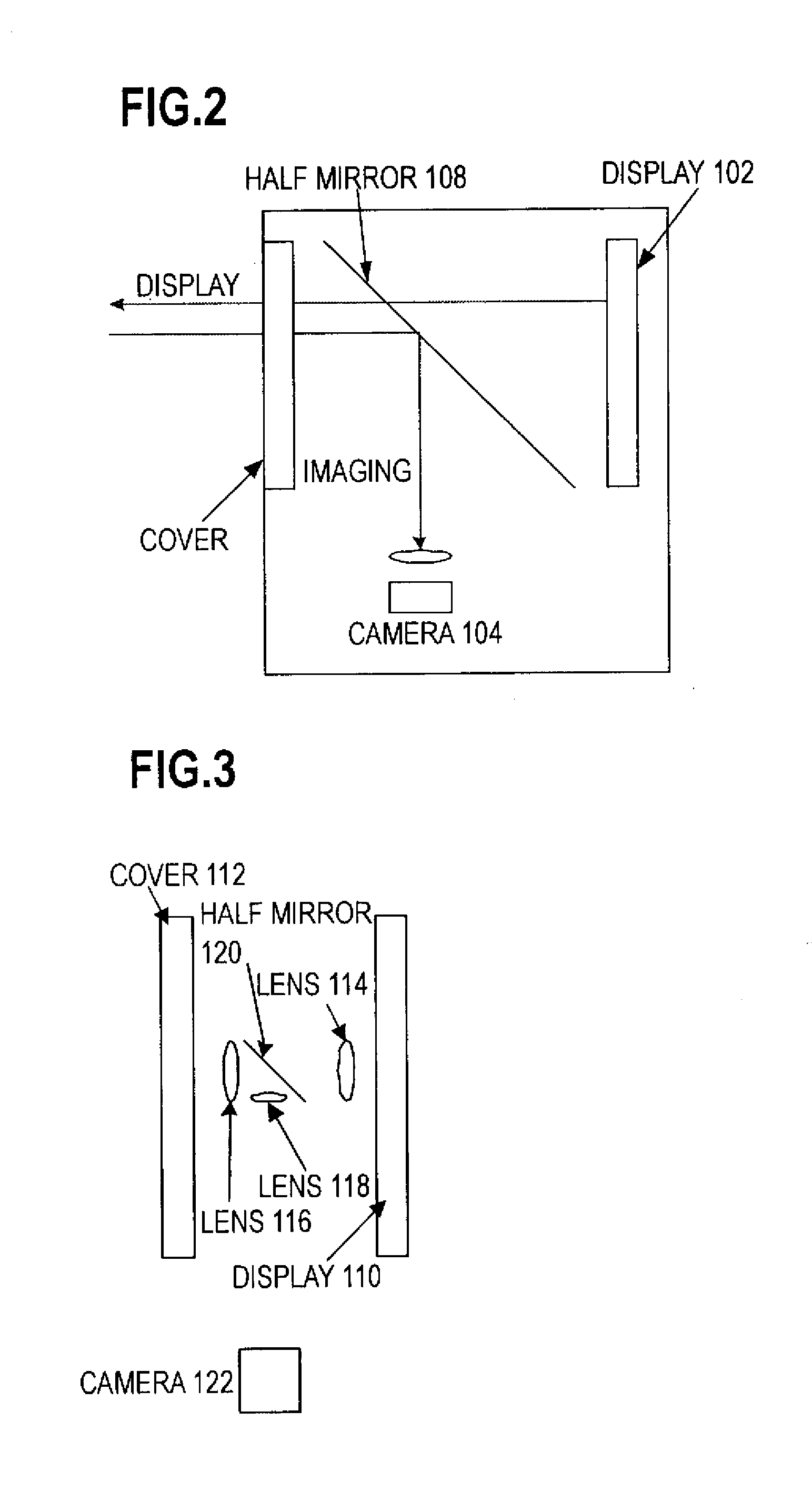
[0034]FIG. 3 shows a diagram illustrating a first exemplary configuration of a lens & halt mirror portion of a videophone apparatus, according to an embodiment of the present invention. The videophone apparatus according to the present invention is, for example, a mobile phone terminal having a built-in camera, and by means of the communication function of the mobile phone terminal, the communication of an image data imaged by the camera is carried out. FIG. 3 is a cross-sectional view of a lens & half-mirror portion of the mobile phone terminal, and the lens & half mirror portion includes lenses 114, 116, 118 and a half mirror 120. Between a display 110 of the mobile phone terminal and a cover (formed of, for example, a glass material) ...


PUM


Abstract

Between a display of a videophone apparatus and a cover thereof, there are disposed lenses 114, 116, 118 and a half mirror, having sufficiently small areas as compared to the surface areas of the display and the cover. The half mirror enables light from the display to transmit to the cover, and reflects light from the outside, so as to lead to a camera. The camera is disposed at a position at which the light reflected by the half mirror can be imaged. Lenses 114, 116 are disposed in opposite positions sandwiching the half mirror. Light from the display passes through lens 114, transmits through the half mirror, and further, passes through lens 116, so as to be led to the cover. Also, light from the cover passes through lens 116, and is reflected by the half mirror, and then passing through lens 118, so as to be led to the camera.

Description

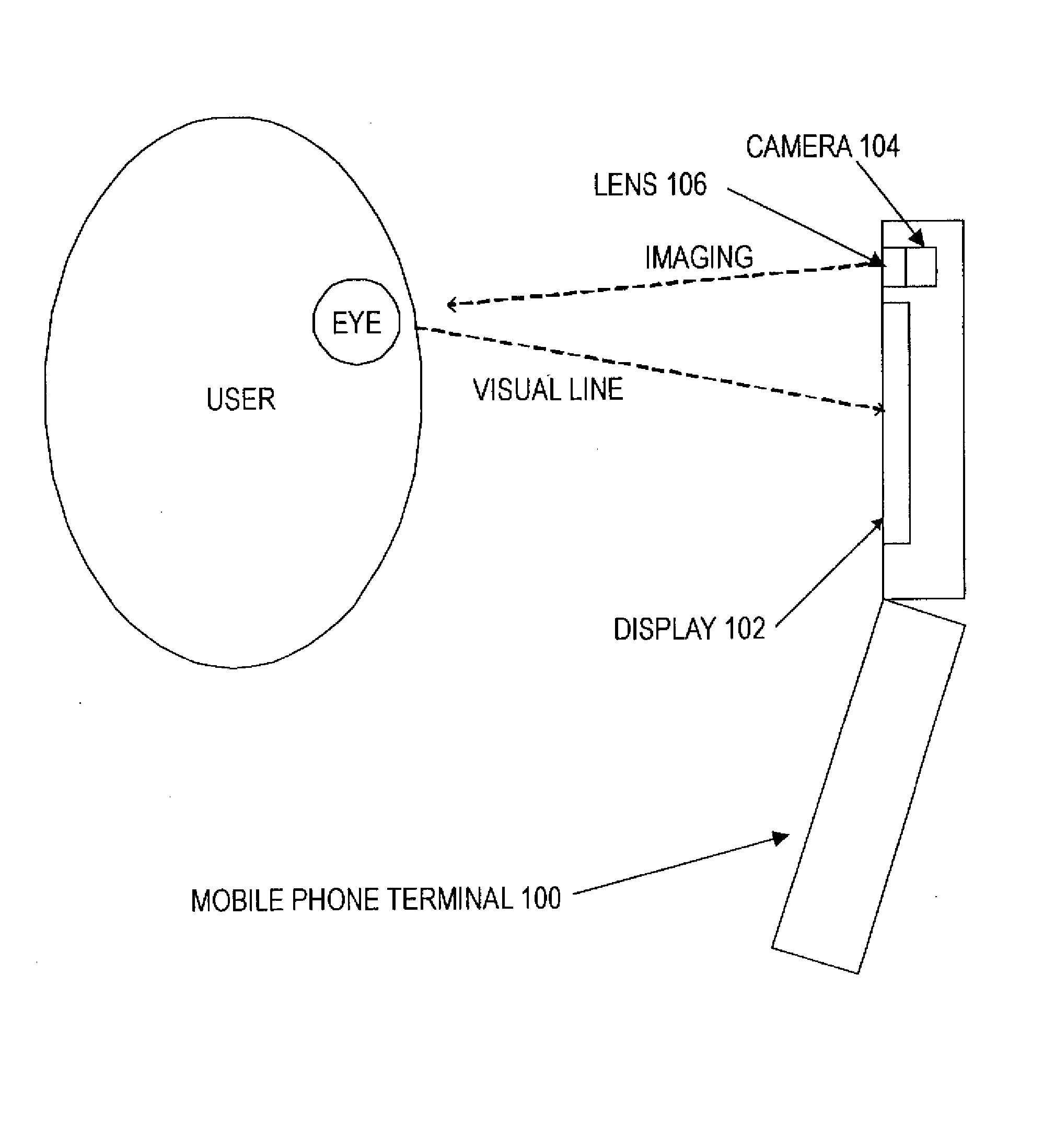
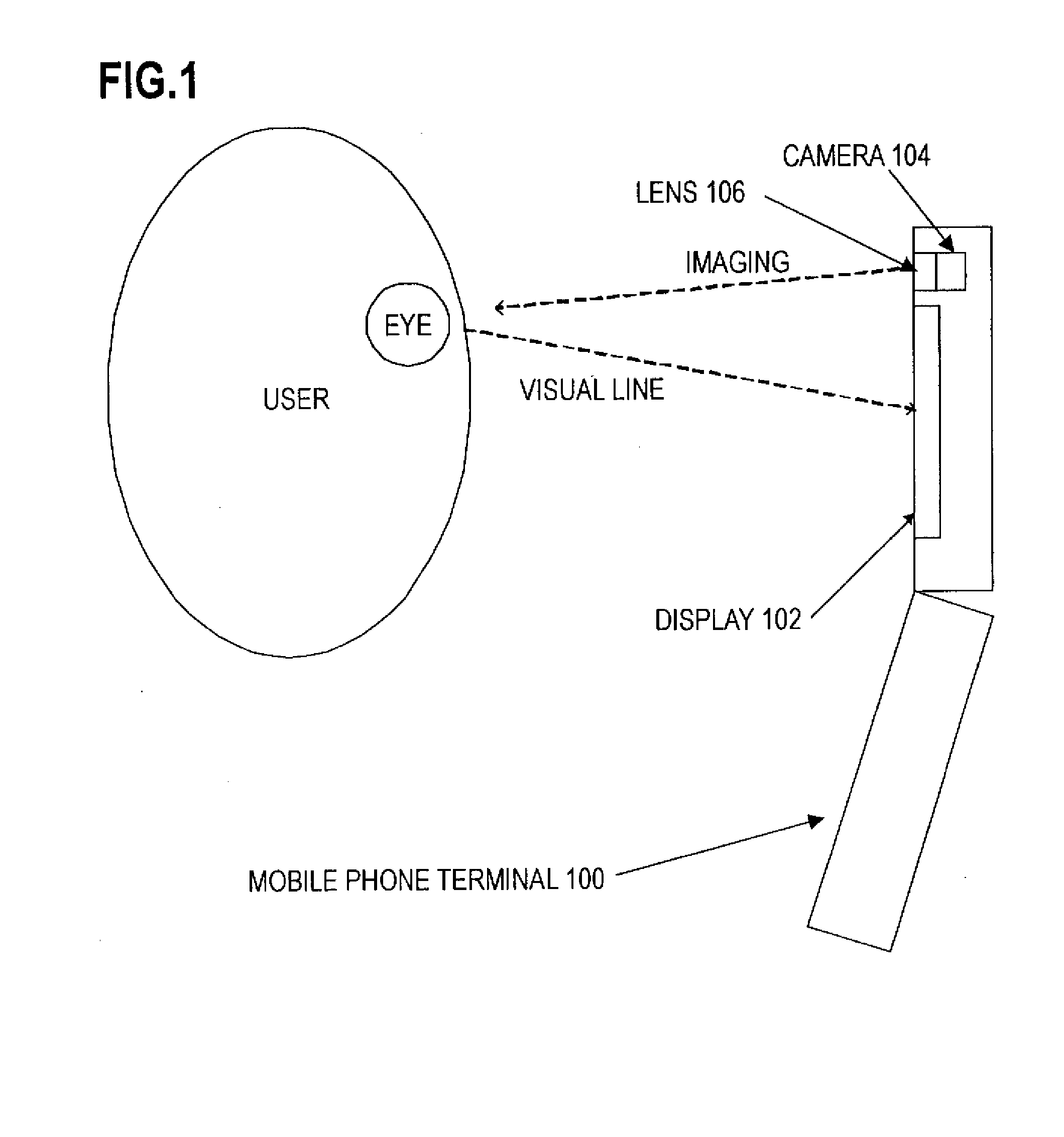
CROSS-REFERENCE TO RELATED APPLICATIONS [0001] This application is based upon and claims the benefit of priority from the prior Japanese Patent Application No. 2006-302316, filed on Nov. 8, 2006, the entire contents of which are incorporated herein by reference. BACKGROUND OF THE INVENTION [0002] 1. Field of the Invention [0003] The present invention relates to a videophone apparatus, and more particularly a small-sized thin videophone apparatus mountable on a small-sized mobile terminal such as a mobile phone terminal. [0004] 2. Description of the Related Art [0005]FIG. 1 shows a diagram illustrating an example of the conventional mobile phone terminal with a videophone function. A mobile phone terminal 100 includes a display 102 and a camera 104, and a lens 106 is disposed in a different position from display 102. Camera 104 images, for example, a user face through lens 106, and the imaged image is transmitted to the terminal of the other communication party. At this time, since t...

Claims


Application Information

Patent Timeline
IPC IPC(8): H04N7/14
CPCH04N2007/145H04N7/144
Inventor MIKAMI, JUNYA
Owner FUJITSU LTD
Learn More