Apparatus and method for interlocking blocks
Inactive Publication Date: 2008-05-15
BUSE JAY
53 Cites 10 Cited by
AI-Extracted Technical Summary
Problems solved by technology
However, most such systems result in blocks that are difficult to manufacture on a large-scale basis, and often the blocks have protrusions such as keys that are prone to breaking during transport and handling, and p...
Abstract
An improved block for making a horizontal, vertical, uneven and/or undulating surface has opposed upper and lower surfaces and opposed side surfaces. Sleeves extend through the block from opposed side surfaces and the sleeves on one pair of sides are at a different elevation from the sleeves at the other pair of sides. When blocks are placed to define a surface the sleeves align with sleeves in adjacent blocks and connecting ties are inserted through the sleeves to interconnect and stabilize the blocks. The blocks are preferably manufactured from concrete.
Application Domain
StrutsWalls +3
Technology Topic
EngineeringMechanical engineering
Image
Examples
- Experimental program(1)
Example
[0014]As noted above, the present invention defines an improved block that incorporates a system for interconnecting adjacent blocks to define a system for use in covering either horizontal or vertical surfaces such as patios, driveways, walls and walkways and the like. Regardless of their particular description, such surfaces are referred to generally herein as “surfaces.” The blocks according to the present invention are preferably manufactured from concrete and may be made with any type of finish, color, design and three-dimensional configuration. However, other materials may be used to manufacture blocks incorporating the invention. As detailed below, the blocks may be placed on flat, sloped or undulating horizontal surfaces, on vertical surfaces, and virtually any other kind of surface topography.
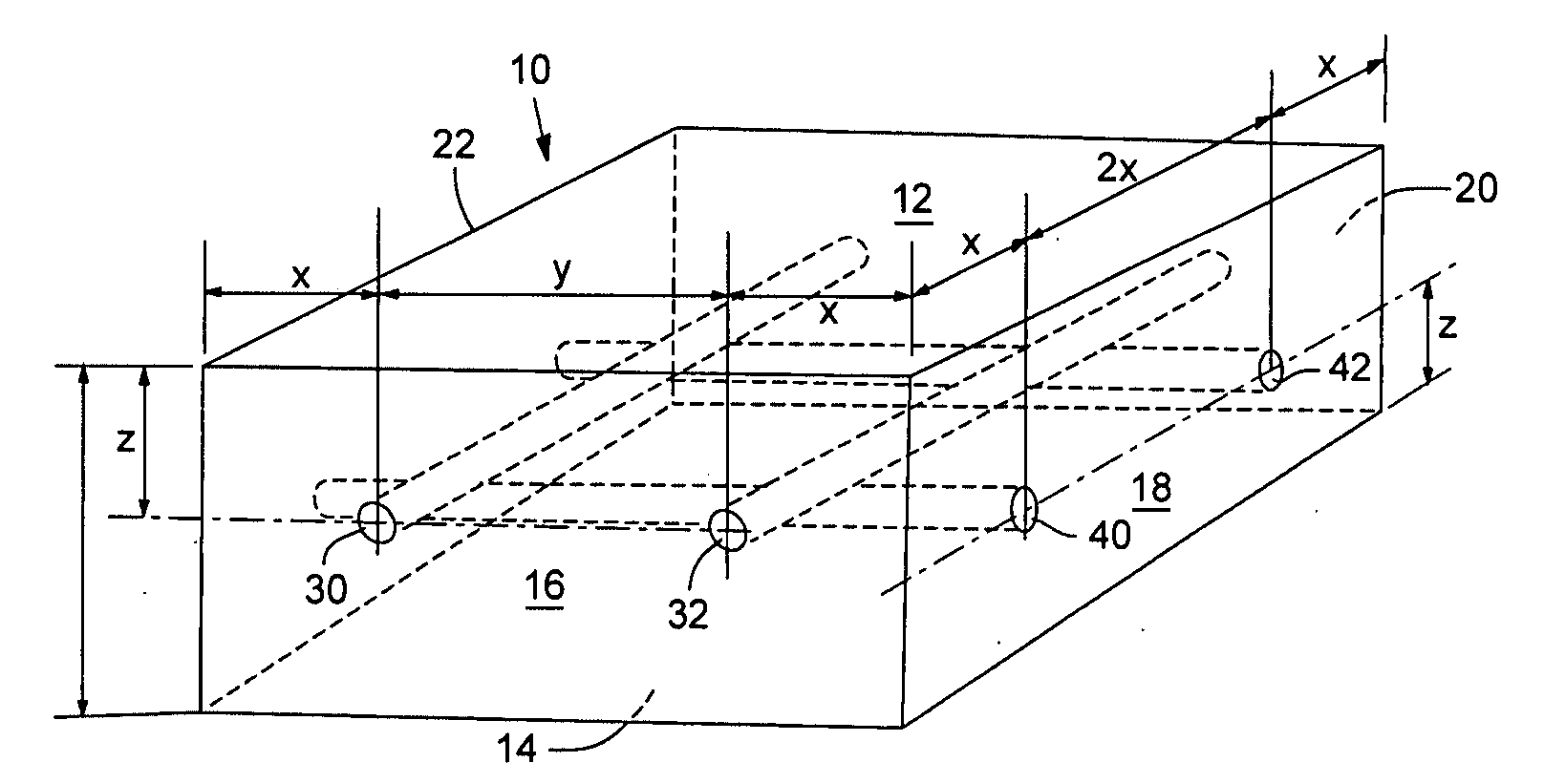
[0015]With reference to FIG. 1, a typical block 10 according to the present invention is shown as being generally rectangular in shape and having therefore six surfaces, namely, upper surface 12, lower surface 14, and four adjacent side surfaces 16, 18, 20 and 22. Relative directional terms used herein are used with reference to the ground plane. Thus, “upper” surface 12 refers to the surface of block 10 that would be the exposed surface when the block was laid into driveway, etc. “Lower” surface 14 would thus refer to the surface opposite upper surface 12, and would be the surface that rests against the grade onto which the block is placed. Although block 10 is shown as being generally rectangular, the block incorporating the present invention may be of virtually any geometric configuration. Moreover, although the “upper” edges of the block are shown as being right angles, the corners could be rounded or sculpted into any desired configuration; the rectangular shape shown in the figures is to illustrate and embody the invention and is not meant to limit its scope.
[0016]With continuing reference to FIG. 1, a pair of sleeves 30 and 32 extends through block 10 from side surface 16 to opposite side surface 20. Similarly, a pair of sleeves 40 and 42 extends through block 10 from side surface 18 to opposite side surface 22. The sleeves 30 and 32 are positioned parallel to one another and at the same elevation in block 10, and sleeves 40 and 42 are also parallel to one another but transverse to sleeves 30 and 32. Thus, sleeves 30 and 32 are positioned in the block such that the axis through the sleeves is parallel to the plane defined by upper surface 12, and such that the axis through each of the sleeves is equidistant from the upper surface 12. Sleeves 40 and 42, which as noted are transverse to sleeves 30 and 32, are at a different—in this case lower—elevation from sleeves 30 and 32. Thus, sleeves 40 and 42 are positioned in block 10 such that the axis through the sleeves is parallel and parallel to the plane of the upper surface 12, and such that the axis through the sleeves is equidistant from upper surface 12. However, the distance from the axis through sleeve 40 to upper surface 12 is different from the distance from the axis through sleeve 30 to the upper surface 12.
[0017]Block 10 is manufactured so that the distance between any corner and the center of the sleeve nearest that corner is the ½ the center-to-center distance between two adjacent sleeves. As shown in FIG. 1, which includes exemplary dimensions, the sleeves 30 and 32 are spaced apart from one another by a distance designated with dimension Y. In a real block, this dimension might be 4 inches, but as detailed herein, that actual dimension could vary widely. The distance from the axial centerline through sleeve 30 to the corner that is defined by the intersection of sides 16 and 22 is thus ½ Y, and is identified in the drawings with dimension X. Continuing with the example just illustrated where Y is 4 inches, X would be 2 inches, and the distance from the axial centerline through sleeve 32 to the nearest corner, that is, the corner between sides 16 and 18 would similarly be 2 inches. This convention is applied to all blocks 10, regardless of their shape. Thus, if block 10 is larger than the block shown in FIG. 1 and has three sleeves on any one side, the distance between sleeves is Y and the distance from a corner to the nearest sleeve is X, and X is ½Y. All blocks manufactured according to the present invention are compatible with one another through use of this convention.
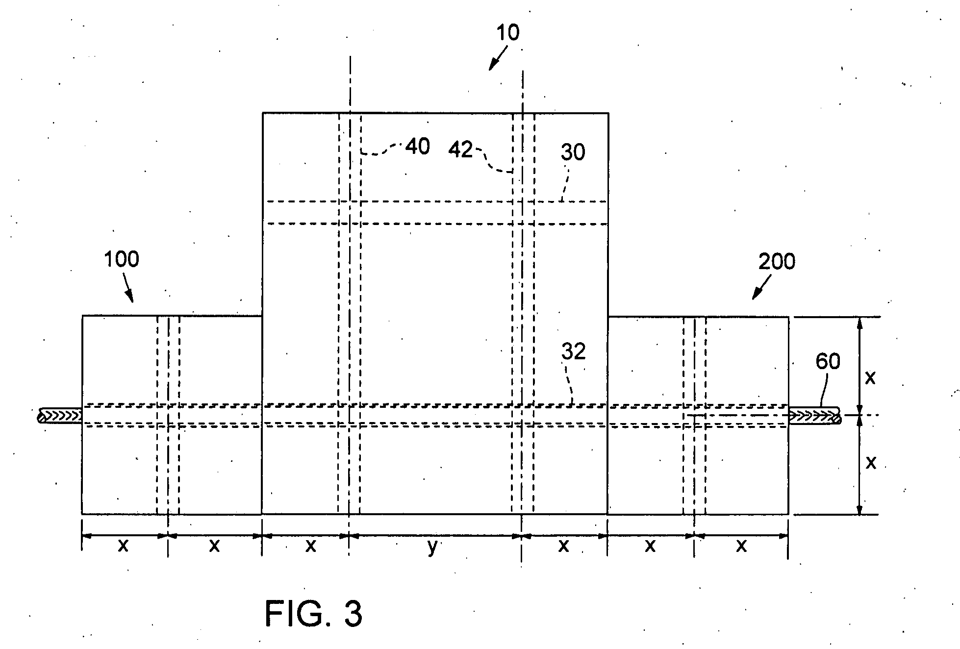
[0018]In other words, the spacing of sleeves in blocks that are designed to be used together is the same for all blocks in a set, although the spacing between sleeves need not be 4 inches as exemplified above and the spacing between sleeves to corners thus need not be 2 inches. The result of this structure is that regardless of which size blocks are used, or when blocks of different size are used to create a surface, the sleeves (or sleeve) in one block always align with the sleeves (or sleeve) in adjacent blocks. This principal is illustrated in FIG. 3, which shows three blocks 10, one of which is larger than the other two, and in the case of FIG. 3, the larger block 10 is twice the size of the two other blocks. Regardless, it may be seen that the sleeve in the two smaller blocks align with sleeve 40 in the center, larger block.
[0019]With continuing reference to FIG. 1, the distance from the centerline or axis through sleeves 30 and 32 to upper surface 12 of block 10 is designated as distance Z. The distance from the centerline or axis through sleeves 40 and 42 to lower surface 16 of block 10 is identical, and is therefore identified with dimension Z. As detailed above, therefore, while the distance from the axis through sleeve 40 to upper surface 12 is greater than the distance from the axis through sleeve 30 to upper surface 12, the distance from the axis through sleeve 40 to lower surface 16 is equal to the distance from the axis through sleeve 30 to upper surface 12—distance Z.
[0020]In the event all blocks 10 are manufactured with the same thickness (i.e., the distance measured from the upper surface 12 to the lower surface 14), then the dimension Z may be calculated as (0.5)(block thickness)—radius of the sleeve. This of course assumes that the sleeves are located in the block such that the sleeves are directly next to one another in the vertical direction in the block rather than spaced apart from one another. If the sleeve in this formulation is not defined by raw concrete as detailed below, but is instead defined by an insert that becomes part of the block, then the wall thickness of the insert is added to the radius of the sleeve in the equation.
[0021]Again, the actual size dimensions used to make blocks 10 does not matter so long as the relative relationships between the dimensions described above are adhered to. Thus, it will be appreciated based on the foregoing that blocks 10 may be made of various dimensions so long as all sleeves at a first elevation are spaced the same, and all transverse sleeves at a second elevation are also spaced the same. The sleeves at the first elevation may be placed at any distance from the upper surface 12, and likewise, the transverse sleeves may be placed at any distance from lower surface 16 so long as the transverse sleeves do not interfere with the other sleeves and so long as the distance from the sleeves to the respective nearest upper or lower surface is equal.
[0022]Sleeves 30, 32 and 40, 42 are formed when block 10 is formed in a cast. The sleeves may be formed as an insert with actual tubing formed into the concrete material, such as metal, plastic, PVC tubing or composite materials, or the sleeves may be formed as raw holes in the concrete material. As such, the sleeves define holes through the blocks regardless of whether a separate material is used to define the sleeve, or the sleeve is defined by a hole formed in the material that forms the block. Regardless of the method used to form the sleeves, the interior diameter of all sleeves is preferably the same. Blocks 10 are formed in molds. When tubes such as PVC tubing are used for the sleeves, the tubes are positioned in the empty molds in the desired positions. Wet concrete is then filled into the molds. Once the concrete sets, the molds are removed and if any excess tubing extends beyond the side surfaces of the block, the excess is removed. Alternately, when the sleeves are formed as openings in the concrete, solid rods that are slidable in the molds are positioned such that the rods extend through the molds in the desired positions and orientations corresponding to the positions of the sleeves. Concrete is then poured into the molds and prior to complete set of the concrete, but after the concrete is sufficiently set and can hold its shape, the rods are removed by pulling them out of the molds. This leaves through openings in the blocks that serve as the sleeves.
[0023]The grade upon which the blocks are laid is prepared according to local codes and building rules. Typically, the grade will be leveled and a layer of crushed and compacted gravel will suffice as the grade and will provide a good base for the blocks.
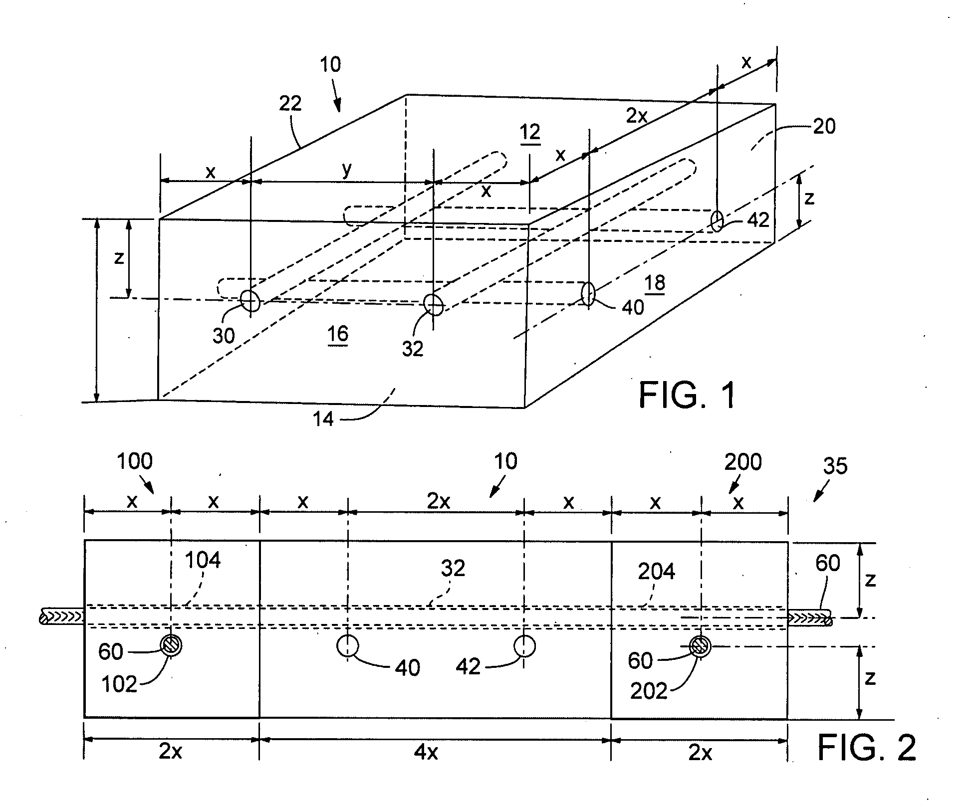
[0024]When more than one block 10 is laid adjacent another block, the two blocks are oriented relative to one another such that the side of the block having the sleeves at a first elevation (e.g., 30, 32) faces the side of the adjacent block that has the sleeves at the same first elevation. More than one block oriented next to adjacent blocks as shown in FIG. 2 thus defines a surface 35, which could be a driveway, patio or any other surface. In this way, the sleeves of one block align with the sleeves of the adjacent block. Similarly, when the blocks are thus arranged, the adjacent sides of the block have sleeves that align with sleeves at the same elevation in adjacent blocks.
[0025]With reference now to FIG. 2, three blocks 10, 100 and 200 are shown. Block 10 is identical to block 10 in FIG. 1, but blocks 100 and 200, which are of the same thickness as block 10, are ½ the size measured around the perimeter and thus have only one sleeve running between opposed sides—sleeves 102 and 104 in block 100, and sleeves 202 and 204 in block 200. It may be seen that sleeves 102 in block 100, 40 and 42 in block 10, and 202 in block 200 are at the same elevation. Thus, the distance Z measured from the axial centerline through the sleeves to the lower surface of the blocks is the same for each of the blocks. Transverse sleeves 104, 32 and 204 on the other hand are at a different elevation, but as described above, the distance from the axial centerline through the sleeves to the upper surface of the blocks is Z. Accordingly, all sleeves align with sleeves in adjacent blocks as described above.
[0026]With blocks laid in place as shown in FIG. 2, connecting ties, referred to herein as ties 60 are inserted through the sleeves in each block. The connecting ties 60 have an outside diameter that is slightly smaller than the inside diameter of the sleeves so that the ties slide easily into the sleeves, yet make substantial connections along the length of the sleeves between the tie and the interior surface of the sleeve. The connecting ties 60 interconnect adjacent blocks and substantially stabilize a group of adjacent blocks. Connecting ties 60 may be metallic, plastic, composite or other materials and may be of sufficient length to interconnect any two or more adjacent blocks. Alternately, the ties 60 may be relatively longer so that the tie together many adjacent blocks. This is typically done on relatively large, flat surfaces. At a minimum, the ties should be long enough that they are inserted into the aligned sleeves of two adjacent blocks. This connection provides the minimum satisfactory stability to the surface.
[0027]The material used for the ties may be somewhat flexible, particularly when relatively long sections are used. This allows the tie to be inserted into the sleeves of many adjacent blocks even where the surface is undulating or uneven.
[0028]It will be understood that the diameter of ties 60 and the interior diameter of the sleeves 30, 32, etc. may be varied so long as the relative difference between the diameter of the tie and the diameter of the sleeve is fairly close. As noted, this allows the ties to be easily slid into the sleeves, yet insures good contact between the tie and the sleeve, thus insuring good stabilization of the surface.
[0029]Connecting ties 60 may also be rigid, such as with metal rods, or flexible as with steel rope or cable.
[0030]A surface covered with blocks 10 interconnected with connecting ties 60 according to the present invention may be horizontal, vertical, flat or undulating. The sleeves described above serve not only to accept connecting ties 60, but also may serve as reinforcement for the blocks.
[0031]As detailed in FIG. 4, blocks10 may be of many different dimensions may be square, rectangular or otherwise. For example, a block with a side face that is 16 inches long and with 4 inch sleeve-to-sleeve spacing would have 4 sleeves. A 12 inch block with 4 inch sleeve to sleeve spacing would have 3 sleeves, and so on.
[0032]The upper surface of the block 10 may be finished in any desired manner, such as exposed aggregate, broom finish, rough or smooth finish. The corners of the block may be beveled, radiused, or may be at 90 degrees.
[0033]The sleeves may be either straight tubular as shown in FIG. 1, or may be tapered as illustrated in FIG. 5, where sleeve 400 in block 402 increases in diameter from side 404 toward opposite side 406. The connecting tie 60 is shown as being anchored in sleeve 400 near side 404; by anchoring the connecting tie 60 in block 402 the stability of the surface is increased. The connecting tie may be anchored with a threaded fastener or clamp 408 applied to the connecting tie 60 externally of the sleeve 400, or with adhesives 410 and the like applied to the interior of the sleeve 400.
[0034]It will be understood that the fastener 408 may be used with sleeves that are not tapered. Ideally, at least one end of each connecting tie 60 will be anchored to a block. When plural blocks are thus interconnected with plural connecting ties, there will be a compressive load placed on adjacent blocks that strengthens the surface. In this regard, with one end of a connecting tie anchored to a block, the opposite end may be similarly connected to a block that may be adjacent or many blocks separated from the anchor block, and the opposite end may be anchored to the associated block with the connecting tie put under tension (as with a threaded fastener such as 408). This compresses the plural blocks to provide strength.
[0035]The block 402 in FIG. 5 also illustrates and example of a block that has a dimension Z between the centerline through sleeves 30, 32 and 33 to the lower surface of the block is one distance (i.e., distance Z), but where the distance from the centerline of sleeve 400 to the opposite, upper surface of the block is different—in this case, distance M. It will be appreciated that with the block shown in FIG. 5, all blocks must be oriented appropriately for the sleeves to align in adjacent blocks, and that sleeves 30, 32 and 33 in FIG. 5 will always be oriented the same way—that is, either toward the ground or to the upper surface. In contrast, with the blocks illustrated in FIGS. 1 through 3, where the distance Z is the same for all sleeves measured from the sleeves to the nearest adjacent surface, the blocks may be rotated 180 degrees so that the upper surface becomes the lower surface, with no effect on the alignment of the sleeves.
[0036]As illustrated in FIG. 6, two connecting ties 60′ and 60″ have threaded ends that are interconnected with a threaded coupler 61. The coupler 61 securely interlocks the ends of adjacent ties and further stabilizes the surface. Other methods of attaching the ends of ties may be used, such as welding or adhesives. When a coupler such as coupler 61 is positioned intermediately along the length of a sleeve, such as illustrated in FIG. 6, the diameter of the sleeve may be stepped from a larger diameter to accommodate the coupler, which is greater in diameter than the tie, to a relatively smaller diameter that is closer to the diameter of the tie.
[0037]Finally, in FIG. 7 a plurality of blocks 500, 502, 504, and 506 are placed in a vertical stack on a base 508, which typically is a concrete footing. The blocks shown in FIG. 7 define a retaining wall that holds back soil 520. Typically drain tile such as tile 522 is used to provide good drainage. Each block 500, 502, 504 and 506 may be arranged so that it is vertically staggered relative to adjacent blocks, or some other pattern. Regardless of the relative orientation of the blocks, each of the blocks has a vertically oriented sleeve 510 that aligns with the sleeve 510 in the adjacent block, and with a receiving sleeve 512 in base 508, and each block includes a horizontally oriented sleeve 514. A connecting tie 516 runs through the aligned vertical sleeves and is anchored in base 508. Similarly, a horizontally oriented connecting tie extends through each sleeve 514 (shown with reference numbers 519, 524, 526 and 528 in FIG. 6), as detailed above with the other embodiments.
[0038]While the present invention has been described in terms of a preferred embodiment, it will be appreciated by one of ordinary skill that the spirit and scope of the invention is not limited to those embodiments, but extend to the various modifications and equivalents as defined in the appended claims.
PUM


Description & Claims & Application Information
We can also present the details of the Description, Claims and Application information to help users get a comprehensive understanding of the technical details of the patent, such as background art, summary of invention, brief description of drawings, description of embodiments, and other original content. On the other hand, users can also determine the specific scope of protection of the technology through the list of claims; as well as understand the changes in the life cycle of the technology with the presentation of the patent timeline. Login to view more.