
Sewing device for sewing sealing material with base materials

a technology of sealing material and base material, which is applied in the direction of sewing apparatus, pressers, textiles and paper, etc., can solve the problems of leaking foaming agent, difficult to precisely set and retain such narrow sealing material at a given sewing point on the top of those base materials, and small width strip of sealing material per s

Inactive Publication Date: 2008-05-29
TACHI S CO LTD
View PDF11 Cites 19 Cited by
  • Summary
  • Abstract
  • Description
  • Claims
  • Application Information

AI Technical Summary

Benefits of technology

[0010]In view of the afore-stated drawbacks, it is a purpose of the present invention to provide an improved sewing device for sewing strip (s) of sealing material (s) with two base materials, which is capable of sewing such strip (s) of sealing material (s) With two base materials automatically and precisely.

Problems solved by technology

This kind of foamed product integral with trim cover assembly, such as armrest or headrest, has been with the problem that, during the foaming process, the liquid foaming agent is leaked out through pinholes formed by sewing needle in at least one sewn connection portion in the trim cover assembly which is preformed by sewing two separate base materials together.
However, such strip of sealing material per se is quite small in width and assumes a very narrow strip or tape.
As a result, certainly, the two juxtaposed base materials can be set at a given sewing point by simply abutting all the edges of the base materials against a guide member and be easily sewn with each other, with a constant margin to seam, but, it is difficult to precisely set and retain such narrow sealing material at a given sewing point upon the top of those base materials.
It is therefore actually impossible to precisely sew the sealing material with the two base materials along such constant margin to seam.
Further, in the case that the strip of sealing material underlies the two base materials, the strip of sealing material per se is not viewed and can in no way be positioned at the given sewing point, as a result of which, it is impossible to precisely sew the sealing material with the base materials along a predetermined sewing path or line.

Method used


Image

  • Sewing device for sewing sealing material with base materials
  • Sewing device for sewing sealing material with base materials
  • Sewing device for sewing sealing material with base materials

Examples


Embodiment Construction

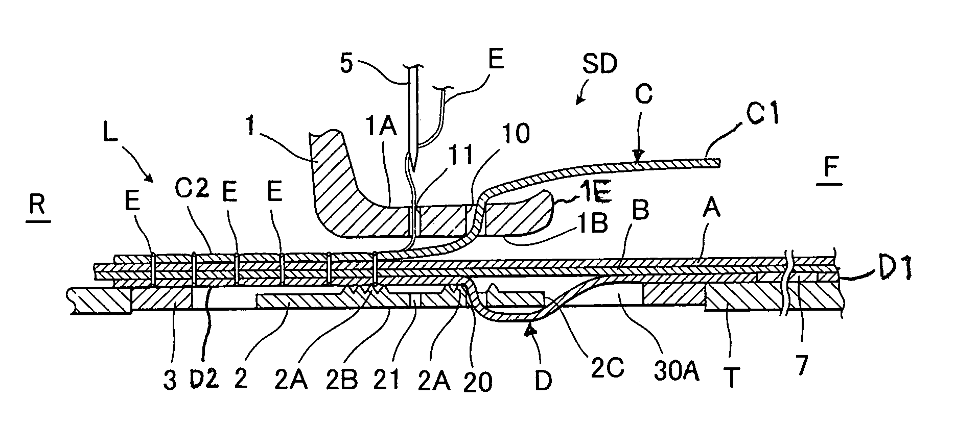
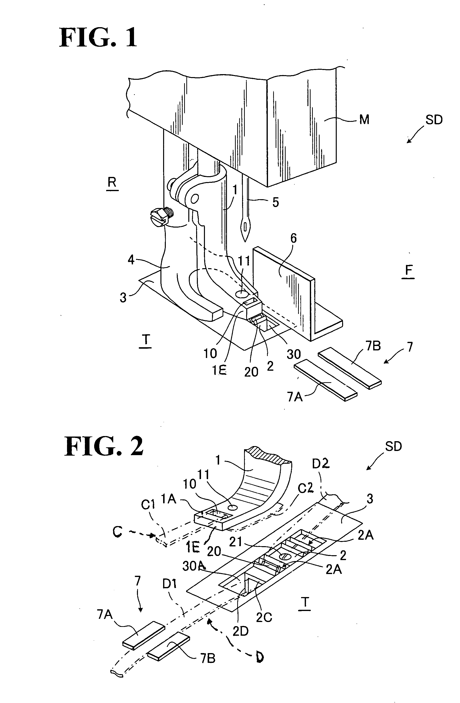
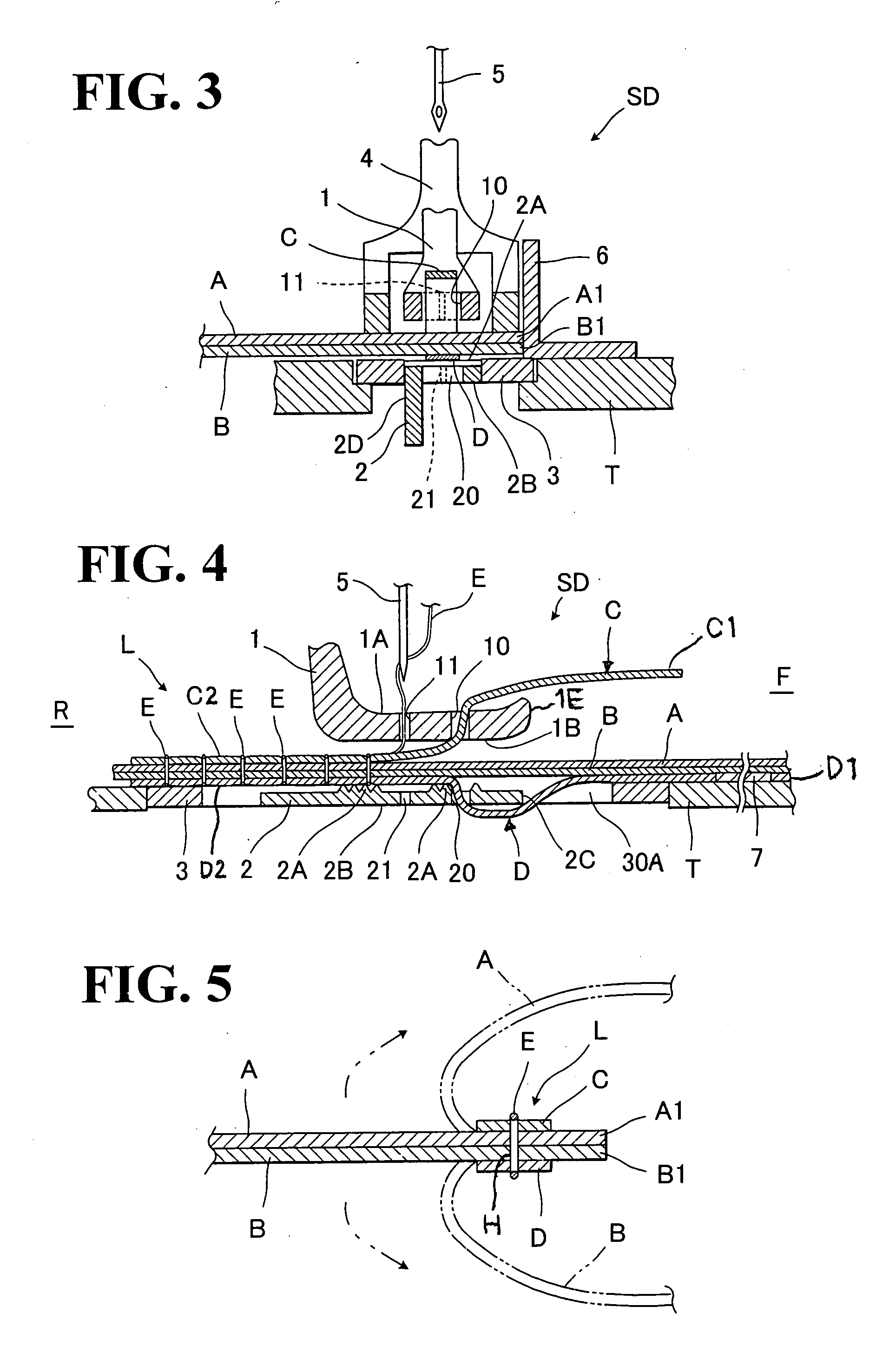
[0030]Referring to FIGS. 1 through 7, there is illustrated a preferred embodiment of sewing device (SD) in accordance with the present invention, which is so designed that first and second separated base materials are sewn together, while at the same time, one or two strips of sealing material stated previously is / are sewn with those two separate base materials.

[0031]In this regard, designations (A) and (B) denote a first base material and a second base material, respectively, which are to be sewn together along their respective two end portions (A1) and (B1) by the sewing device (SD). Also, designations (C) and (D) denotes a first strip of sealing material and a second strip of sealing material, respectively. Each of such two strips of sealing materials (C) and (D) is the same as the strip of sealing material (e.g. a sealing strip or a sealing tape) explained in the foregoing description of prior art and are therefore intended to seal each pinhole formed in the first and second bas...


PUM


Abstract

Sewing device for sewing first and second strips of sealing materials with respective first and second base materials. A first guide through-hole, through which the first strip of sealing material passes, is formed in a presser foot of the sewing device adjacent to a needle hole formed in the latter. A second guide though-hole, through which the second strip of sealing material passes, is formed in a feed dog member of the sewing device at a point adjacent to that needle hole. In operation, while the first and second base materials are fed by and between the presser foot and feed dog member, the first and second strips of sealing materials are simultaneously fed together with the first and second base materials, while being precisely guided by the respective first and second guide through-holes for sewing with the respective first and second base materials.

Description

BACKGROUND OF THE INVENTION[0001]1. Field of the Invention[0002]The present invention relates to a sewing device for sewing together base materials into a three-dimensional trim cover assembly which is for example used for forming a headrest or armrest for use on an automotive seat. In particular, the invention is directed to a sewing device capable of sewing together two base materials along with a strip of sealing material which includes a resin sealing tape or strip.[0003]2. Description of Prior Arts[0004]Many of armrests or headrests for use on automotive seat are formed by a typical process which comprises the steps of: sewing separate base materials together to form a three-dimensional trim cover assembly conforming to a predetermined shape of armrest or headrest; placing the thus-formed three-dimensional trim cover assembly in a foaming die; injecting a liquid foaming agent into the inside of the trim cover assembly; and curing that liquid foaming agent into an increased mass...

Claims


Application Information

Patent Timeline
Patent Type & Authority Applications(United States)
IPC IPC(8): D05B27/00D05B39/00
CPCD05B27/00D05B35/02D05B29/00
Inventor KOBAYASHI, YUKIHITO
Owner TACHI S CO LTD
Learn More