System and method for controlling lighting

a lighting system and lighting control technology, applied in the field of lighting, can solve problems such as affecting the progress or improvement of lighting systems, complicating installation and/or operation of such systems, and still needing to be resolved

Inactive Publication Date: 2008-06-12
KONINKLIJKE PHILIPS ELECTRONICS NV
View PDF29 Cites 203 Cited by
  • Summary
  • Abstract
  • Description
  • Claims
  • Application Information

AI Technical Summary

Benefits of technology

[0010]An object of the invention is to provide a system and method for controlling lighting. In accordance with an aspect of the invention, there is provided a system for controlling generation of light from one or more light-emitting elements in response to an external input, the system comprising: a control interface module configured to receive the external input and convert same in accordance with a predefined internal control protocol, and a light generation module communicatively linked to said control interface module and operatively linked to the one or more light-emitting elements for controlling same in accordance with said converted input.
[0011]In accordance with another aspect of the invention, there is provided a method for controlling generation of light from one or more light-emitting elements of a lighting device in response to an external input, the method comprising the steps of: receiving the external inp...

Problems solved by technology

Some challenges, however, still need to be resolved to adapt current and upcoming LED technology to general illumination applications.
Other challenges arise from the diversity of control systems and processes implemented in the art, such that incompatibilities between systems and/or products provided by different parties who may favour a different control standard or pro...

Method used


Image

  • System and method for controlling lighting
  • System and method for controlling lighting
  • System and method for controlling lighting

Examples


example 1

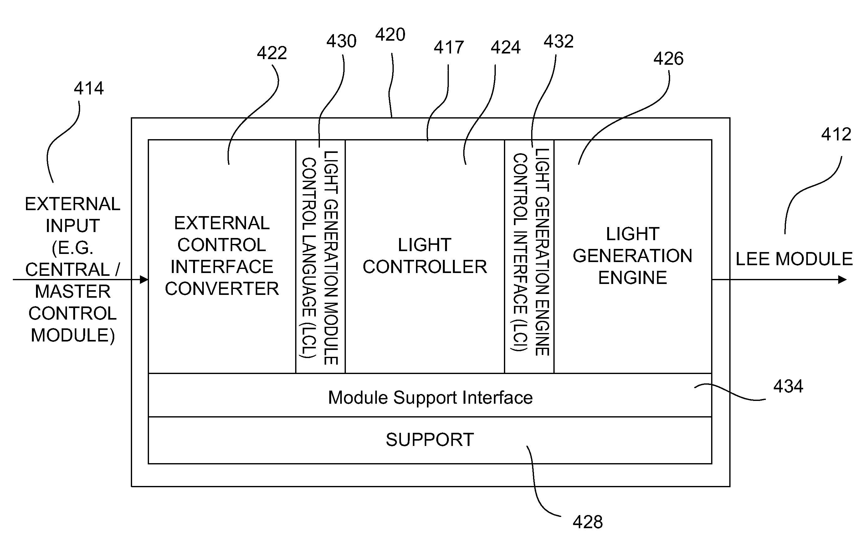
[0183]FIG. 7 shows the firmware architecture for an integrated drive and control system 620 comprising a combined control interface / light generation module 617, in accordance with one embodiment of the invention. The module 617 generally comprises an ECIC 622 configured to receive an external input 614 and convert same in accordance with the LCL 630. The converted LCL commands are then communicated to a light controller 624 operatively linked to an LGE 626 via a LCI 632 for generation of a controlled light output via light-emitting element module(s) 612.

[0184]In this embodiment, all components other than the ECIC 622 interface directly with the light controller to exchange the needed LCL commands and responses. Access to a private network 619 is optionally provided to allow connection to a distinct control interface module and / or light generation module in order to implement external controls not implemented within the control interface / light generation module 617.

[0185]The module f...

example 2

[0186]FIG. 8 shows the firmware architecture for a distributed system 720 comprising a distinct control interface module 716 and light generation module 718. In this embodiment, a number of the firmware components are duplicated so that each module 716, 718 comprises its own copy (e.g. network protocol stack 740, module control 744, real time framework 750, reflash-in-place 760, etc.).

[0187]In this embodiment, the external input 714 is connected to the ECIC 722 of the control interface module 716, which is responsible for converting this input into LCL 730 and communicate this converted input to the light controller 724 of the light generation module 718 via a private network 719 and appropriate network stacks 740. Once received, the light controller 724, interfacing with a LGE 726 via LCI 732, may then proceed in cooperatively controlling generation of light from the light-emitting element module(s) 712.

[0188]As in the above, example, the control interface module 716 and light gene...

example 3

[0189]FIGS. 9 and 10 provide an example of a distributed system comprising a control interface module 816 (see FIG. 9) communicatively linked to a light generation module 818 (see FIG. 10) via a private network 819. The control interface module 816 is illustratively comprised of a multiple interface board, which, in this example, can be manufactured to provide one of three options, each one of which supporting a single external input 814: DALI, DMX, or 4-Button Manual Control (e.g. see also Example 8 with reference to FIG. 23).

[0190]In this example, the control interface module 816 supports a single private network 819 which may be used to communicate MCL 848 and RP 860 to the control interface module 816, and transport LCL 830, MCL 848 and RP 860 traffic between the ECIC 822, external module control interface 842 and module control 844 of the control interface module 816, and the light controller 824 (and indirectly the LGE 826) and module control 844 of the light generation module...


PUM


Abstract

A system and method for controlling lighting are described. In general, the system and method may be used for controlling generation of light from the one or more lighting devices within a lighting system, in response to an external input. The control system generally comprises a control interface module and a light generation module. The control interface module is configured to receive the external input and convert same in accordance with a predefined internal control protocol. The light generation module is communicatively linked to the control interface module to receive the converted input and is operatively linked to the one or more light-emitting element modules for controlling generation of light thereby in accordance with the converted input. In one example, the light generation module is either interchangeable or interchangeably adaptable to receive the external input in accordance with one of two or more control protocols.

Description

FIELD OF THE INVENTION[0001]The invention pertains to the field of lighting and in particular to a system and method for controlling lighting.BACKGROUND[0002]Advances in the development and improvements of the luminous flux of light-emitting devices such as solid-state semiconductor and organic light-emitting diodes (LEDs) have made these devices suitable for use in general illumination applications, including architectural, entertainment, and roadway lighting. Light-emitting diodes are becoming increasingly competitive with light sources such as incandescent, fluorescent, and high-intensity discharge lamps. For example, various LED-based light sources, which may include different combinations of LEDs and optionally other light-emitting devices and / or luminous devices / materials, can be used and controlled to provide a desired output.[0003]Further LED-based light sources have been disclosed to comprise a feedback system enabling such light sources to adjust an output of the light-sou...

Claims


Application Information

Patent Timeline
IPC IPC(8): H05B37/02F21K9/00H05B44/00
CPCH05B37/0254H05B47/18H05B45/20
Inventor ROBINSON, SHANE P.BJELJAC, BOJANASMITH, DUNCAN L. B.POLI, STEFAN
Owner KONINKLIJKE PHILIPS ELECTRONICS NV
Why Eureka
Try Eureka