Strip lighting system incorporating light emitting devices

a technology of light emitting devices and strip lighting, which is applied in the direction of lighting and heating equipment, lighting support devices, instruments, etc., can solve the problems of high voltage, high labor intensity, and inability to meet the needs of licensed tradesmen for installation and replacement,

Inactive Publication Date: 2005-04-19
SIGNIFY HLDG BV
View PDF17 Cites 201 Cited by
  • Summary
  • Abstract
  • Description
  • Claims
  • Application Information

AI Technical Summary

Problems solved by technology

They are fragile, high voltage, energy consuming, monochromatic devices with inconsistent life patterns.
They are labour intensive and require licensed tradesmen for installation and replacement.
This type of placement of adjacent housings however, produces dark spots within the separation region and therefore a continuous contour of light may not be perceived.
However, upon the placement of these types of devices in an environment in which there will be thermal gradients, the nature of these devices through the incorporation of a plurality of different materials and therefore varying thermal expansion coefficients, in addition to the potential end to end placement thereof, can result in potential problems.
These problems can include leakage and breakage of the units due to differential expansion of the various components, in addition to a discontinuous light contour being created if thermal expansion is not accounted for in the placement of the devices.

Method used


Image

  • Strip lighting system incorporating light emitting devices
  • Strip lighting system incorporating light emitting devices
  • Strip lighting system incorporating light emitting devices

Examples


Embodiment Construction

Definitions

[0025]The term “light emitting device” is used to define light emitting diodes, high flux or high brightness light emitting diodes or any other form of semiconductor device enabling the creation of illumination.

[0026]Unless defined otherwise, all technical and scientific terms used herein have the same meaning as commonly understood by one of ordinary skill in the art to which this invention belongs.

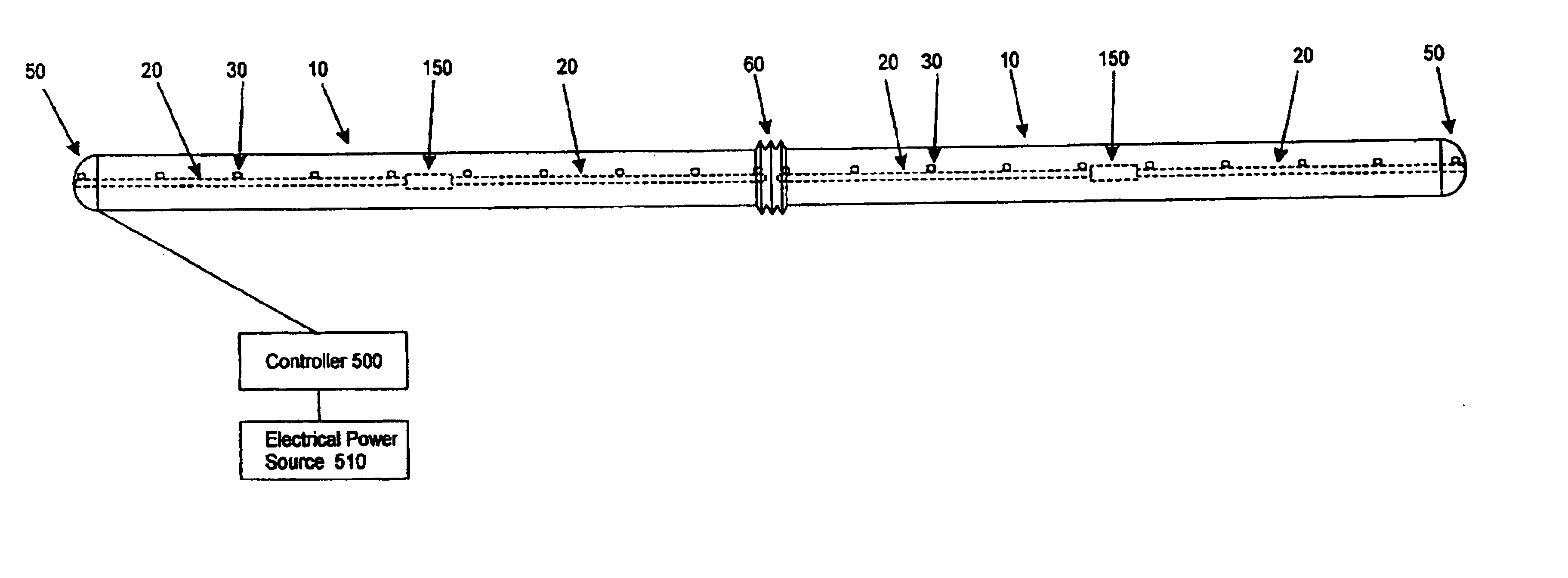
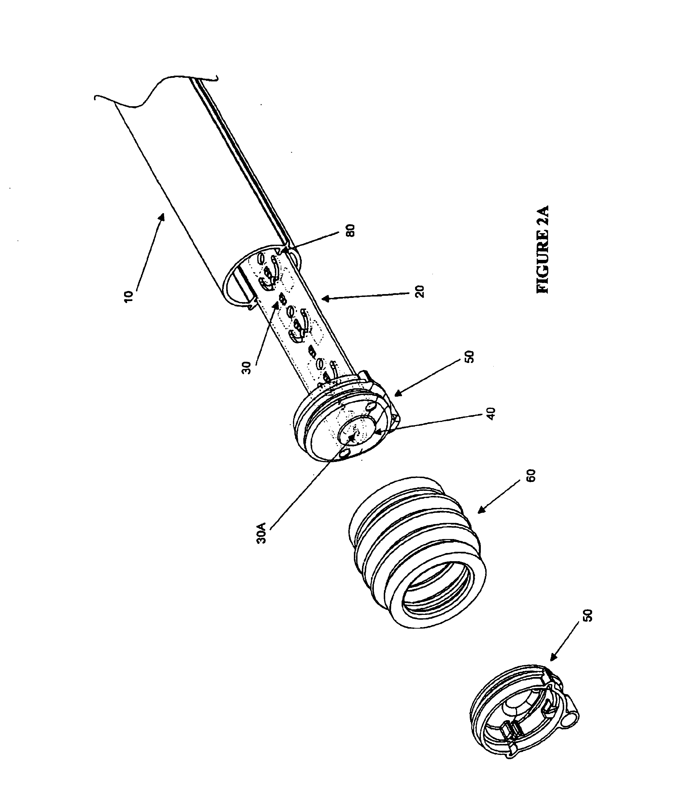
[0027]The present invention provides an elongated lighting apparatus for use in environments subject to temperature fluctuations, wherein the lighting apparatus can be illuminated along its entire length during operation. The elongated lighting apparatus comprises several components which operate in harmony in order to provide this functionality. The lighting apparatus comprises at least two elongated tubular members fabricated from a material that allows the passage of light therethrough. These elongated tubular members are fixedly mounted on a surface in an end to end config...


PUM


Abstract

The invention provides an elongated lighting apparatus that can withstand temperature fluctuations. The elongated lighting apparatus comprises of the following elements: at least two elongated tubular members fabricated from translucent material. These elongated tubular members are fixed in an end-to-end configuration, separated by a region enabling for thermal expansion / contraction of the members. A substrate upon which a plurality of light emitting devices is placed, is slidably positioned inside each tubular member. End caps seal the open ends of the elongated tubular members. At least one of these end caps has a translucent protrusion that projects towards the region of separation. At least one light emitting device is positioned proximate to an end cap protrusion, thereby illuminating this region. A flexible interconnector encloses and visually conceals separating the adjacent members. The light emitting devices are electrically interconnected. An external power source provides a system to energize the light sources.

Description

FIELD OF THE INVENTION[0001]The present invention pertains to the field of lighting systems and in particular to a strip lighting system incorporating light emitting devices.BACKGROUND OF THE INVENTION[0002]Neon lights are widely used in commercial applications as decorative enhancements and back lights. For example, they are used to highlight architectural features or to display names, logos and the like.[0003]Neon lights are generally chosen for their neon effect or glare which demands the viewer's attention. This ability to draw attention outweighs the many drawbacks associated with neon lights. They are fragile, high voltage, energy consuming, monochromatic devices with inconsistent life patterns. They are labour intensive and require licensed tradesmen for installation and replacement. From a practical standpoint, any other type of lighting would be desirable if it could produce the attention demanding impact associated with neon.[0004]There are several prior art references tha...

Claims


Application Information

Patent Timeline
Patent Type & Authority Patents(United States)
IPC IPC(8): F21S4/00F21V21/005F21V23/06F21V19/00F21V23/00G09F13/22
CPCF21S4/003G09F13/22H05K1/142F21V19/001F21V21/005F21V23/06F21V19/003H05K2201/10106F21Y2101/02F21S4/20F21Y2115/10
Inventor KAN, PETERWESTON, ADRIAN
Owner SIGNIFY HLDG BV
Why Eureka
Try Eureka