Light emitting diode lighting system

a technology of light-emitting diodes and lighting systems, which is applied in the direction of instruments, catheters, discharge tubes, etc., can solve the problems of lack of flexibility in the placement of design components in the system, and achieve the effect of enhancing light emission

Inactive Publication Date: 2008-08-14
INTEMATIX
View PDF99 Cites 201 Cited by
  • Summary
  • Abstract
  • Description
  • Claims
  • Application Information

AI Technical Summary

Benefits of technology

[0013]In one arrangement the phosphor is coated in layer form on at least a part of a light emitting surface of the waveguide, for example an end surface of an elongate waveguide. Alternatively, the phosphor is embedded in particulate form in at least a portion of the waveguide medium. Moreover, the light emitting surface of the waveguide can further includes a surface topology to enhance emission of light from the surface such as a roughening of the surface or a regular pattern.

Problems solved by technology

While such lighting system designs may have demonstrated properties that are acceptable to some customers, properties such as intensity, color temperature and color perception, for instance, they lack flexibility in how the design components may be placed in the system.

Method used


Image

  • Light emitting diode lighting system
  • Light emitting diode lighting system
  • Light emitting diode lighting system

Examples


Embodiment Construction

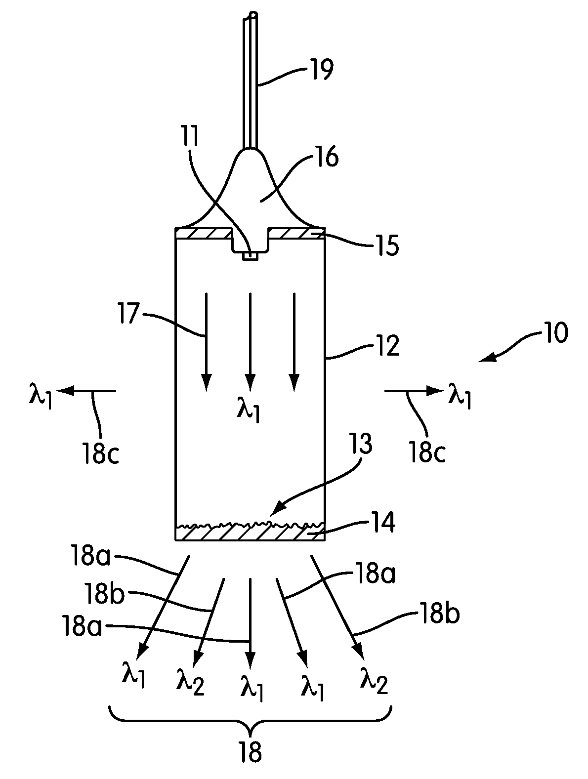
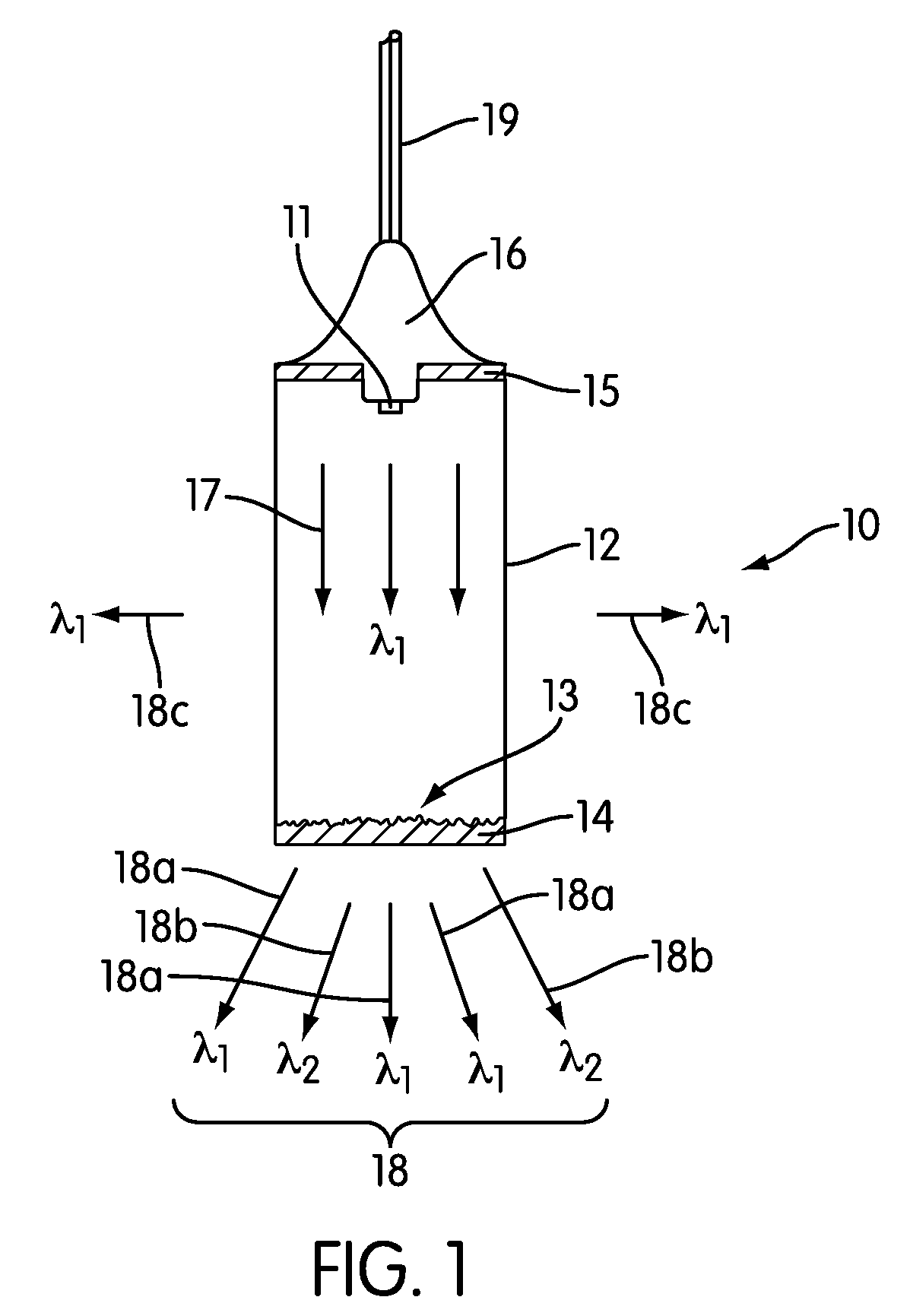
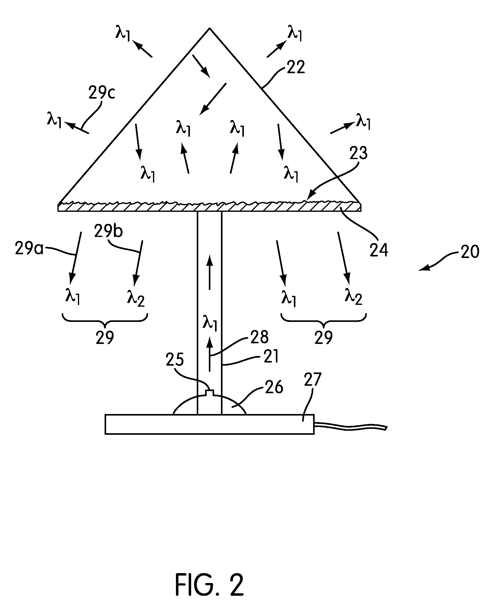
[0028]According to the present embodiments, a lighting system comprises three components: 1) an excitation source, typically a blue or UV emitting LED, 2) a remotely located phosphor, photo luminescent, material which may be coated as a layer on or incorporated in a system component, and 3) a waveguide media for transporting excitation radiation from the excitation source to the phosphor. In these embodiments the blue (e.g. 460 nm) emitting LED serves two purposes: one is to function as a source of excitation radiation needed to cause luminescence of the remotely located phosphor and the second is to contribute to the light which forms the final illumination product. The waveguide media can be either solid or liquid in form, but is most often solid to most efficiently guide or transport the excitation radiation. Simultaneously, the waveguide (or parts thereof) may carry the blue / UV light from the LED chip that is not absorbed by a phosphor, this light instead contributing to the ill...


PUM


Abstract

A lighting system for generating an illumination product comprises an excitation source, blue / UV LED, operable to generate excitation radiation and a remotely located phosphor, photo luminescent material. Excitation radiation is guided from the excitation source to the phosphor by a waveguiding medium, the waveguiding medium being configured such that the distance the radiation travels from the excitation source to the phosphor layer is at least one centimeter in length. The UV / blue excitation source provides excitation radiation to the phosphor(s), causing the phosphor(s) to photo luminesce, and it may also provide a component of the final illumination product. The configuration of the waveguide allows a greater flexibility in lighting system configurations, such as hanging lighting fixtures, desk lighting fixtures, floor standing lighting fixtures, desk lamps, track lighting, spot lighting, accent lighting, lighting panels, inspection lamps and endoscopes.

Description

CROSS REFERENCE TO RELATED APPLICATIONS[0001]This application claims priority to U.S. Provisional Application Ser. No. 60 / 901,837 filed Feb. 12, 2007 entitled “Illumination systems comprising UV / blue excitation radiation waveguided to a remotely located phosphor” which is incorporated by reference herein in its entirety.BACKGROUND OF THE INVENTION[0002]1. Field of the Invention[0003]The field of the invention is directed to Light Emitting Diode (LED) lighting / illumination systems / fixtures or luminaires. More specifically, the present embodiments are directed to LED lighting systems with phosphor, photo luminescent, wavelength conversion to generate a desired color of light.[0004]2. Description of the Related Art[0005]The introduction of solid state semiconductor devices such as semiconductor light emitting diodes (LEDs) has allowed a new generation of energy efficient lighting systems to come into existence. Today, most lighting fixture designs utilizing LEDs comprise systems in whi...

Claims


Application Information

Patent Timeline
Patent Type & Authority Applications(United States)
IPC IPC(8): F21V9/16H01J1/62
CPCA61B1/0653A61B5/0084A61B5/4547F21S6/002F21S8/02F21S8/033G02B6/005F21S8/06F21Y2101/02F21Y2105/00G02B6/0008G02B6/0021F21S8/04F21V14/06F21Y2115/10G02B6/0001
Inventor LI, YI-QUN
Owner INTEMATIX
Why Eureka
Try Eureka