System and method for operating an internal combustion engine with hydrogen blended with conventional fossil fuels

a technology of hydrogen and internal combustion engine, which is applied in the direction of machines/engines, electrical control, mechanical equipment, etc., can solve the problems of prohibitive deployment, no commercial success, and inability to retrofit existing ic engines using these systems, so as to reduce emissions in existing ic engines without affecting performance and longevity, and inexpensive rep.

Active Publication Date: 2005-10-20
OREILLY HUGH
View PDF13 Cites 81 Cited by
  • Summary
  • Abstract
  • Description
  • Claims
  • Application Information

AI Technical Summary

Benefits of technology

[0011] Accordingly, one object of the present invention is to inexpensively replace a large proportion of fossil fuels wit

Problems solved by technology

Various attempts have been made to burn hydrogen and fossil fuel mixtures in IC engines in order to reduce harmful emissions but none have been commercially successful.
Although these engines may operate to provide the intended results of lowering harmful emissions, the cost of retrofitting existing IC engines using these systems has made their deployment prohibitively expensive.
If the fuels are in the same tank, then an existing IC engine cannot perform well under load because the hydrogen displaces the critical amount of natural gas needed for optimal power.
Since hydrogen stored in the same tank with natural gas cannot be selectively substituted, a dual fuel mixture such as this would inhibit engine power and performance when required by the vehicle.
No known systems have been successful beyond experimentation, possibly because they did not properly address the ability of existing engines to accept dual or new fuels, the stoichiometry of blended fuels, lack of electr

Method used


Image

  • System and method for operating an internal combustion engine with hydrogen blended with conventional fossil fuels
  • System and method for operating an internal combustion engine with hydrogen blended with conventional fossil fuels
  • System and method for operating an internal combustion engine with hydrogen blended with conventional fossil fuels

Examples


Embodiment Construction

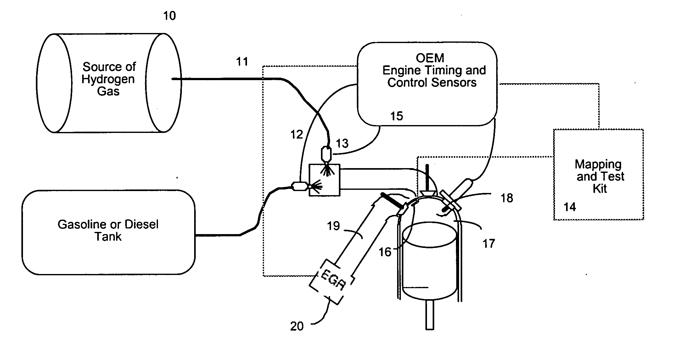
[0028] In order to lighten the following description, the following acronyms will be used: [0029] IC Internal Combustion; [0030] EGR Exhaust Gas Recovery; [0031] NGV Natural Gas Vehicle; [0032] OEM Original Equipment Manufacture

[0033] As indicated above, the substitution of fossil fuels for hydrogen cannot be accomplished economically unless there are incentives from government agencies (which have control over the tax structure of the fuels), to all of the energy industry, the automotive industry and the end user, i.e. the consumer. Given the current lack of such incentives, the main objective of how to promote the use of hydrogen and how to set up the infrastructure to supply a source of hydrogen remains. With the use of the system and method of the present invention, existing vehicles can be modified to make use of hydrogen in an economical way. Further, the addition of hydrogen to existing fuel is a permanent environmental solution because hydrogen will not break down like a ca...


PUM


Abstract

A system for retrofitting an internal combustion engine to use a proportion of hydrogen gas and existing fossil fuel is disclosed. The system is comprised of a source of hydrogen gas and means for delivering hydrogen gas to the combustion chamber of the engine. The engine operating parameters are adjusted and the delivery of hydrogen is controlled to provide selective introduction of hydrogen gas throughout the engine's operating cycle. The source of hydrogen gas can comprise an onboard hydrogen reformer, or hydrogen and carbon monoxide can be reformed inside the cylinder from an on board carrier of hydrogen. A single point injector placed at the intake manifold in close proximity to the engine intake valve can be used to mix the hydrogen gas to the air/fossil fuel mixture or sequential injectors can deliver hydrogen in close proximity to each engine intake valve, or directly into each cylinder.

Description

CROSS-REFERENCE TO RELATED APPLICATION [0001] This application claims priority from U.S. provisional application Ser. No. 60 / 563,616 filed on Apr. 20, 2004, and which is incorporated herein by reference.FIELD OF THE INVENTION [0002] This invention relates generally to the use of hydrogen in an internal combustion engine, and particularly relates to promoting the use of hydrogen in existing internal combustion engines while minimizing engine retrofitting and invasion. BACKGROUND OF THE INVENTION [0003] Great efforts have been spent by the automotive industry to reduce our dependence on fossil fuels. Also, because of regulatory requirements, research continues to reduce emissions of internal combustion (IC) engines, regardless of whether they are powered by conventional gasoline, diesel or natural gas fuels. [0004] In a typical gasoline automobile, the catalytic converter helps to reduce the harmful emissions, but such reductions can still be improved substantially. One of the biggest...

Claims


Application Information

Patent Timeline
IPC IPC(8): C01B3/32C01B3/38F02B23/00F02B43/08F02B43/12F02B45/10F02D19/08F02D41/00F02M25/10
CPCC01B3/323Y02T90/42C01B2203/0233C01B2203/06C01B2203/1223C01B2203/1241F02B43/08F02B43/12F02B45/10F02D19/066F02D19/081F02D41/0025F02D41/0027F02D2400/11F02M25/10Y02T10/34F02D19/0697Y02T10/32F02D19/0644F02D19/0671F02D19/0692Y10S123/12Y02T10/36C01B3/38Y02T90/40Y02T10/30
Inventor LANGE, DAVID
Owner OREILLY HUGH
Why Eureka
Try Eureka