Vehicle torque coordination

a technology of torque coordination and vehicle, which is applied in the direction of braking system, jet propulsion mounting, instruments, etc., to achieve the effects of improving driveability, fuel economy and exhaust emissions, and being less prone to failur

Inactive Publication Date: 2005-03-01
FORD GLOBAL TECH LLC
View PDF16 Cites 84 Cited by
  • Summary
  • Abstract
  • Description
  • Claims
  • Application Information

AI Technical Summary

Benefits of technology

Torque coordination under the present invention is more robust and less prone to failure than conventional systems which use different algorithms for hybrid functions. The present invention also results in improved driveability, fuel economy and exhaust emissions.

Problems solved by technology

The first excess requested torque is compared with the second torque producing device torque production limitations.

Method used


Image

  • Vehicle torque coordination
  • Vehicle torque coordination
  • Vehicle torque coordination

Examples


Embodiment Construction

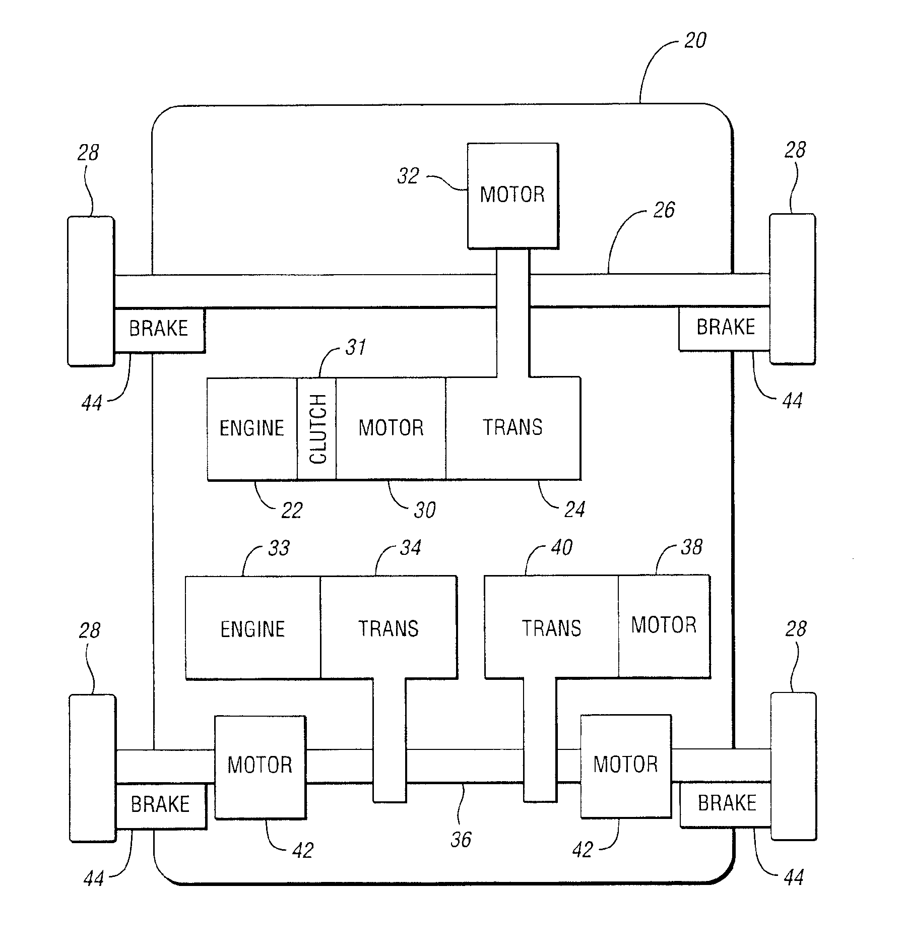
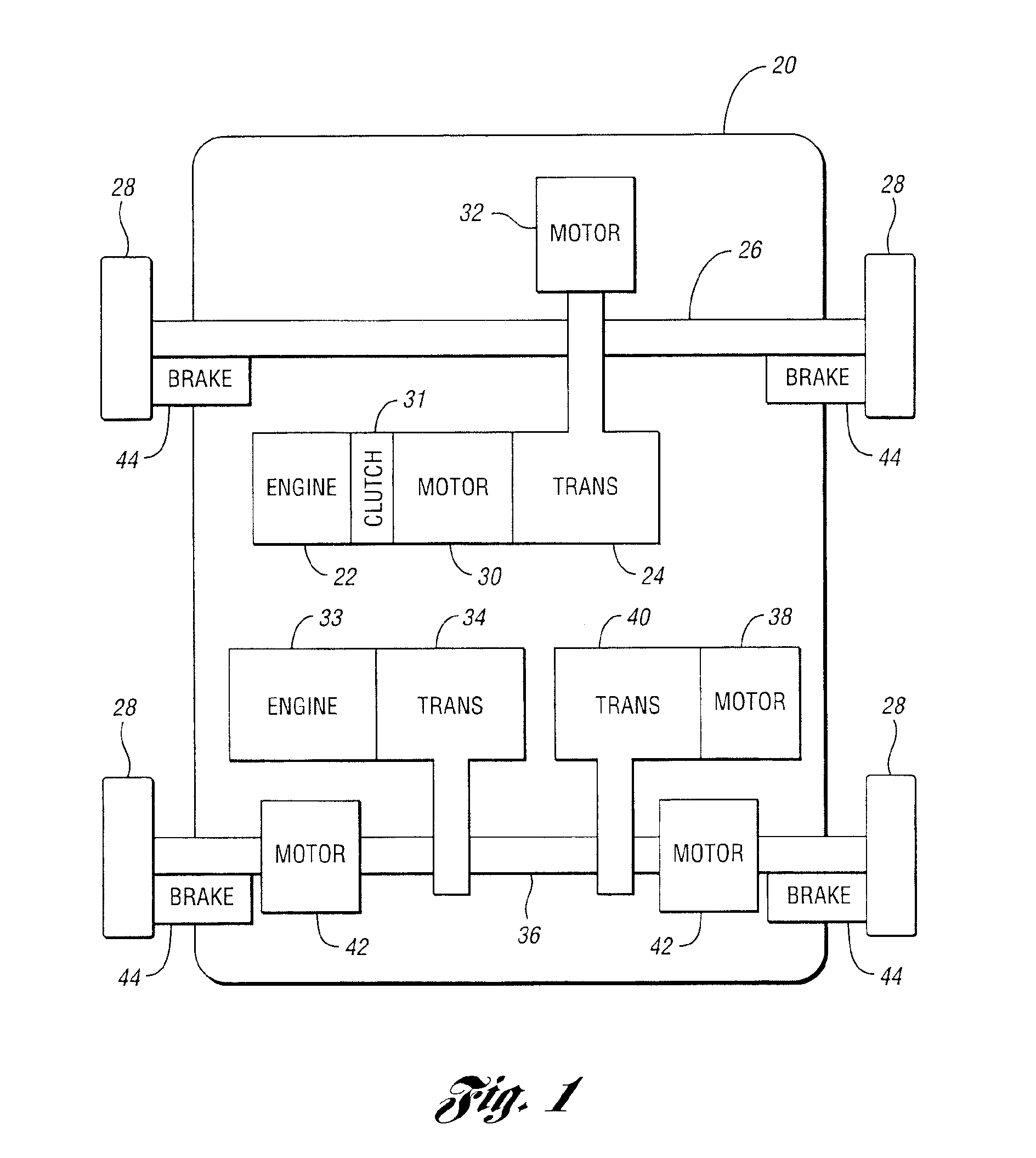
Referring to FIG. 1, a schematic diagram illustrating torque producing devices according to an embodiment of the present invention is shown. Vehicle 20 may include a plurality of torque producing devices. Torque producing devices include any of a wide variety of internal combustion engines (ICE). Various types of motors may also be employed, including those powered by energy storage devices such as batteries, accumulators and the like; powered by power generating devices, such as engines, fuel cell systems, solar cell systems, and the like; or powered by any combination of these.

For example, engine 22 transmits torque through engine transmission 24 to front axle 26 thereby driving wheels 28. Engine transmission 24 is controlled to convert torque from engine 22 to axle 26 using various mechanisms such as torque converters, gears, and the like. Transmission 24 may be manual, automatic, continuously variable, composed of one or more planetary gear sets, or of any other suitable constru...


PUM


Abstract

Torque demand is coordinated in a vehicle. Information defining at least one torque production limitation for a first torque producing device is received. A request for torque is compared with the first torque producing device torque production limitation. If the comparison does not result in the request for torque exceeding a limitation, a first coordinated torque request is determined as the request for torque and a null torque is determined as a second coordinated torque request. Otherwise, a first excess requested torque is determined as the difference between the request for torque and the exceeded limitation, the first coordinated torque request is determined as the exceeded limitation, and the second coordinated torque request is determined as the first excess requested torque.

Description

BACKGROUND OF INVENTION1. Field of the InventionThe present invention relates to the control of torque in a vehicle. More particularly, the present invention relates to coordinating torque demands amongst a plurality of vehicular torque producing devices.2. Background ArtVehicle control systems accept requests from the vehicle driver and various vehicle components as well as output from vehicle parameter sensors. Vehicle controllers use these inputs to generate control signals for vehicle equipment. Conventional control systems applied to automotive vehicle applications were used to improve engine operation in order to reduce vehicle emissions. Since these early attempts, engine controls have continued to grow in complexity as opportunities are identified to make further improvements in performance, emissions, fuel economy, and the like. Since the engine controller is still typically the most complex control system on the vehicle, it remains the primary repository for most new vehic...

Claims


Application Information

Patent Timeline
Patent Type & Authority Patents(United States)
IPC IPC(8): G06F7/00G06F19/00B60K5/08B60K6/48B60K6/52B60K23/08B60W10/06B60W10/08B60W20/00
CPCB60K5/08B60K6/52B60K23/0808B60W10/06B60W10/08B60W20/00B60K6/48Y02T10/6265B60L2240/423B60L2240/486B60T2230/04B60T2260/08B60W2710/0666B60W2710/083B60W2710/105Y02T10/6221Y02T10/6286Y02T10/642Y02T10/62Y02T10/64B60W20/10B60K1/02
Inventor PHILLIPS, ANTHONYYANAKIEV, DIANANORIN, BENGTJERRELIND, JONAS
Owner FORD GLOBAL TECH LLC
Why Eureka
Try Eureka