
Scanner for space measurement

A technology of distance measuring device and measuring equipment, applied in the direction of measuring device, active optical measuring device, adopting optical device, etc., can solve the problems of time-consuming, users cannot perform real-time photography, unbalanced beam deflection unit and bending moment, etc. The effect of low computing performance

Active Publication Date: 2015-04-29
HEXAGON TECH CENT GMBH
View PDF8 Cites 21 Cited by
  • Summary
  • Abstract
  • Description
  • Claims
  • Application Information

AI Technical Summary

Problems solved by technology

The arrangement of the panoramic camera outside the beam deflection unit has various disadvantages: on the one hand, two cameras and two beam paths must be provided for the field of view of the cameras, and on the other hand, positioning the panoramic camera outside the beam deflection unit would Causes severe unbalances and bending moments on the beam deflection unit, for which corresponding countermeasures have to be taken, which incurs additional costs and makes the system susceptible to disturbances when working in the field
[0010] Although it is possible, as disclosed in patent documents DE 10 2010 105 027 A1 and patent document EP 2 620 746 A1, by a camera rotating together with the beam deflection unit, the problems caused by the fixed field of view of the camera with respect to the position in conventional on-axis cameras can be solved. Rotational image issue with camera sensor rotation, but users still can't live-cam
Calibrating such equipment is also time consuming and must be calibrated by the manufacturer
Almost impossible to recalibrate on the spot

Method used


Image

  • Scanner for space measurement
  • Scanner for space measurement
  • Scanner for space measurement

Examples


Embodiment Construction

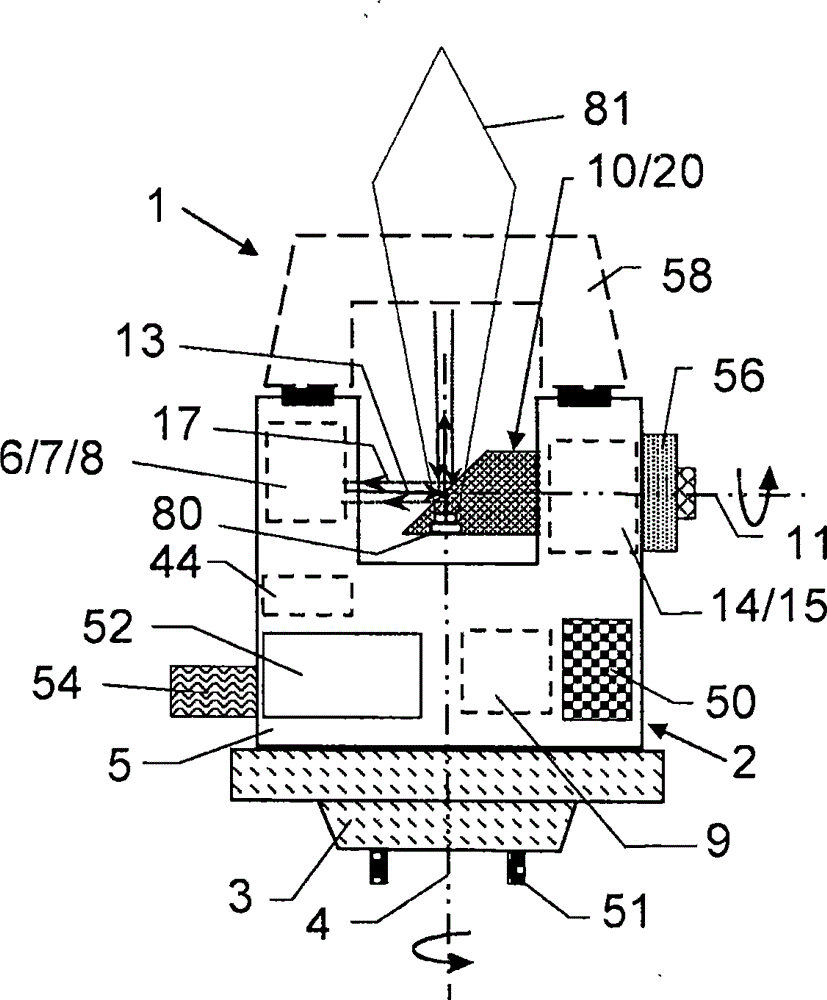
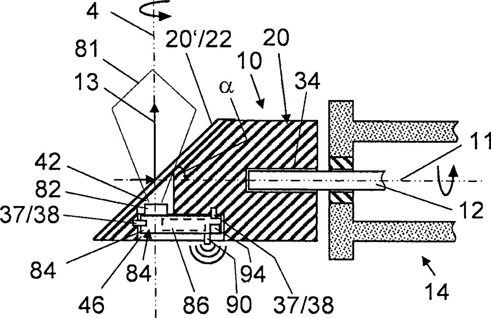
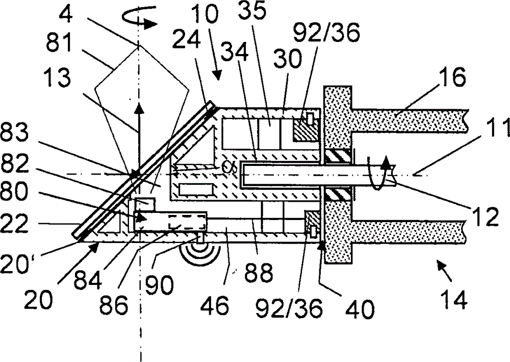
[0086] figure 1 Shown is a first embodiment of a measuring device 1 according to the invention, figure 2 Shown is a detailed view of a beam deflecting unit 10 according to the design of the invention. Generally speaking, the measuring device 1 is equipped with a measuring head 2 , the housing 5 of which is mounted on a base 3 in a manner to be rotatable about a base axis 4 . The base 3 can be fixed on a stand or a tripod by means of an adapter 51 . The base 3 has a base axis 4 about which the housing 5 can be rotated (manually and / or electrically and controlled by a control unit 9 ). A radiation source 6 for generating measuring radiation 13, a detector 8 for detecting reflected radiation 17 received and preferably reflected by a target object, and for propagating the radiation and collimating measuring radiation 13 and reflected radiation 17 The optical assembly 7 is housed in the housing. Both the radiation source 6 and the detector 8 are components of an Electronic Dis...


PUM


Abstract

Some embodiments of the invention relate to a surveying apparatus in the form of a scanner comprising a beam deflection unit, such a beam deflection unit and a measuring method to be carried out with said surveying apparatus. The surveying apparatus comprises a radiation source for generating measurement radiation and a detector for receiving reflected measurement radiation, called reflection radiation for short, which was reflected at an object of interest, wherein measurement radiation and reflection radiation have substantially the same optical path. Situated in said optical path there is a beam deflection unit mounted rotatably about a rotation axis and serving for adjustably aligning the measurement radiation and for capturing the reflected radiation

Description

technical field [0001] The invention relates to a measuring device, in particular realized in the form of a scanning device, in order to generate to scale a three-dimensional image of a measuring object of interest. Background technique [0002] Measuring devices or scanning devices of the type mentioned at the outset are designed for the three-dimensional measurement of spatial regions and / or objects. Typical application examples are the surveying of interior spaces such as churches and workshops, the surveying of large objects such as buildings or aircraft, or forensic surveys of accident scenes. [0003] When measuring these objects, the laser beam of the laser scanning device can be used to scan a predetermined space volume and detect the laser light reflected by the object, wherein the emitted laser beam and the direction of the detected laser light are collected at each moment angle information. The distance between a certain surface point in the volume of space and ...

Claims


Application Information

Patent Timeline
IPC IPC(8): G01B11/00G01S17/86G01S17/89
CPCG01C15/002G01S17/42G01S17/89G01S7/4808G01S7/4813G01S7/4817G01S7/4972G01S7/51G01C15/008G01S17/86G01S17/06
Inventor S·贝斯特勒J·舍加J·辛德林
Owner HEXAGON TECH CENT GMBH
Learn More