Rearview mirror wiper system

a rearview mirror and wiper technology, applied in vehicle maintenance, vehicle cleaning, cleaning equipment, etc., can solve the problems of inability to operate vehicles in inclement weather, prior art devices are not without problems of their own, and the wipers for outside rearview mirrors are not popular, so as to facilitate maintenance and less susceptible to icing

Inactive Publication Date: 2009-08-18
NEMETH GLENN
View PDF20 Cites 21 Cited by
  • Summary
  • Abstract
  • Description
  • Claims
  • Application Information

AI Technical Summary

Benefits of technology

[0012]In one aspect, the invention relates a rearview mirror wiper system suitable for use on, for example, large tractor-trailer trucks (i.e., semi-trailer trucks or semi, colloquially known as a transfer truck, 18-wheeler, semi, or big-rig in the U.S.; as a semi in Australia, and Canada; and as an articulated lorry (artic), or truck and trailer in the UK, Ireland, and New Zealand), delivery trucks, vans, motor homes, cars and other motor vehicles. The rearview wiper system of the present invention has many advantages over prior art systems. It ensures an even and adjustable pressure over the entire wiping surface, has a minimum of parts exposed to the elements so that it is less susceptible to icing and is easy for the user to maintain.
[0013]In one embodiment of the present invention, the rearview wiper system of the present invention contemplates a wiper blade supported at both ends of the blade wherein both ends of the blade are powered at the same speed for even movement across the mirror glass of the rearview mirror. Although the present invention is not limited to any particular mechanism for moving the blade, a preferred mechanism ensures that the blade moves evenly across the glass and with a minimum of jumping or skipping. In this regard, in a preferred embodiment, the wiper system of the present invention is controlled by a pair of drive rods where each drive rod comprises a first and second set of spiral wound grooves that are singularly disposed relative to one another and are connected at the ends thereof and wherein the drive rods are rotated by a motor. The motor may rotate both of the drive rods directly (the preferred embodiment) or may rotate one drive rod with the other drive rod rotating freely as a result of the wiper blade moving across the mirror glass. A tracking device is located on each drive rod that moves along the drive rod as the drive rod is turned by the motor. One end of the wiper blade is attached directly or indirectly to each tracking device. Thus, as the drive rods turn, the tracking devices travel the length of the drive rods by tracking in the first of the spiral would groves in the drive rod and move the wiper blade with them. When the tracking devices reach the end of the drive rods they then track down the second spiral wound grove of the drive rod. Thus, the tracking devices continue to move the wiper blade across the mirror glass of the rearview mirror as long as the motor turns the drive rods. This design solves problems associated with the many of the prior art devices since the wiper blade is drawn evenly across the glass with no or virtually no skipping or jumping.
[0015]This rearview mirror wiper system of the present invention is less prone to failure (than prior art systems, for example) due to, for example, icing because most of the moving parts of the device are protected from the elements by being enclosed in the housing of the device. See, for example, FIGS. 2, 3 and 4. Additionally, in one embodiment of the present invention, it is contemplated that the internal mechanical mechanisms of the present invention are sealed from the elements with flexible flap seals. The flexible flap seals of the present invention are positioned to prevent rain, ice, etc. (i.e., weather elements, weather conditions or precipitation) from entering the housing of the present invention.
[0025]Additionally, in another embodiment of the present invention, said tension device may be designed such that the wiper blade may flip slightly (e.g., by about 2-10 degrees) such that the wiping portion of the wiper blade is trailing the fixed portion of the wiper blade as the wiper blade is pulled across the mirror glass. That the wiping portion of the blade is flexible and / or the wiper is capable of flipping back and forth slightly as the motion of the wiper changes direction across the mirror glass, aids in the wiper clearing the glass of water or other obstructions to the driver's view.

Problems solved by technology

Operating vehicles in inclement weather is difficult and many devices have been developed to aid drivers.
However, wipers for outside rearview mirrors have not become popular even though the safety features of such devices are self-evident.
This is because the prior art devices are not without problems of their own.
This device has two major problems.
First, the mechanism responsible for moving the wiper across the mirror glass is exposed to the elements.
Because of this, the mechanism is prone to corrosion and, in the event of a freezing rain or heavy snow, can become inoperative.
Where such an arrangement may be necessary for windshield wipers it is a disadvantage for wipers on rearview mirrors.
The result is that the wiping action by the wiper is less effective or ineffective when it is needed most leaving, for example, streaks that interfere with visualizing objects with the rearview mirror.
This device has several problems.
This design does not prevent the device from freezing since much of the mechanism is exposed to the elements.
Another problem with the device is that the wiper is moved via an extending telescopic arm that is attached to only one side of the wiper blade.
Such a design is inherently flawed since the trailing end of the wiper blade as well as the wiper itself creates a drag on the system.
This drag results in 1) a burden on the motor and drive system leading to damage of the system and / or premature failure and 12) the uneven cleaning of the mirror glass.
Because of the natural and necessary flexibility of the wiper blade (being made out of a natural or synthetic rubber) the blade and is susceptible to vibration and motion caused by air currents resulting from vehicle movement.
This problem results in the less effective or ineffective cleaning of the mirror glass.
This push rod is susceptible to being rendered inoperable in icy conditions.
U.S. Pat. No. 3,685,081 to Pittman discloses a rearview mirror wiper mechanism but suffers from the design flaw of the wiper being supported on one end only and, thus, is susceptible to wind conditions caused during driving, as are the systems above It also utilizes a complicated and expensive to manufacture double track mechanism within the mirror housing to maintain the blade's horizontal position during use.
This design is subject to freezing solid when exposed to freezing rain or sleet and snow, especially when the vehicle is parked for any length of time.
Because of the plethora of moving parts exposed to the weather, the device would be difficult to clean of ice without damaging the mechanisms.
Thus, this device is also prone to problems caused by icing and wind current causing havoc with the blade leading to uneven cleaning of the mirror surface.
Since a rearview mirror is typically rectangular, this rotating wiper blade design can only clean a small portion of the overall surface area of the mirror leaving a large portion of the mirror uncleaned.
This device suffers from the problem of having the wiper blade supported only on one end of the blade.
This design cannot ensure that the blade receives even pressure along the entire length of the blade thus resulting in uneven cleaning of the mirror glass.
Inherent problems in this device are the loosening and stretching of the cables, cables running off of the pulleys and cables breaking.
Additionally, this device is difficult and expensive to manufacture and difficult to maintain to ensure optimal performance.

Method used


Image

  • Rearview mirror wiper system
  • Rearview mirror wiper system
  • Rearview mirror wiper system

Examples


Embodiment Construction

[0032]The invention will now be described in detail with reference to a few preferred embodiments, as illustrated in accompanying drawings. In the following description, numerous specific details are set forth in order to provide a thorough understanding of the invention. However, it will be apparent to one skilled in the art that the invention may be practiced without some or all of these specific details. In other instances, well-known features and / or process steps have not been described in detail in order to not unnecessarily obscure the invention. The features and advantages of the invention may be better understood with reference to the drawings and discussions that follow.

[0033]While the invention has been described with respect to a limited number of embodiments, those skilled in the art, having benefit of this disclosure, will appreciate that other embodiments can be devised which do not depart from the scope of the invention as disclosed herein.

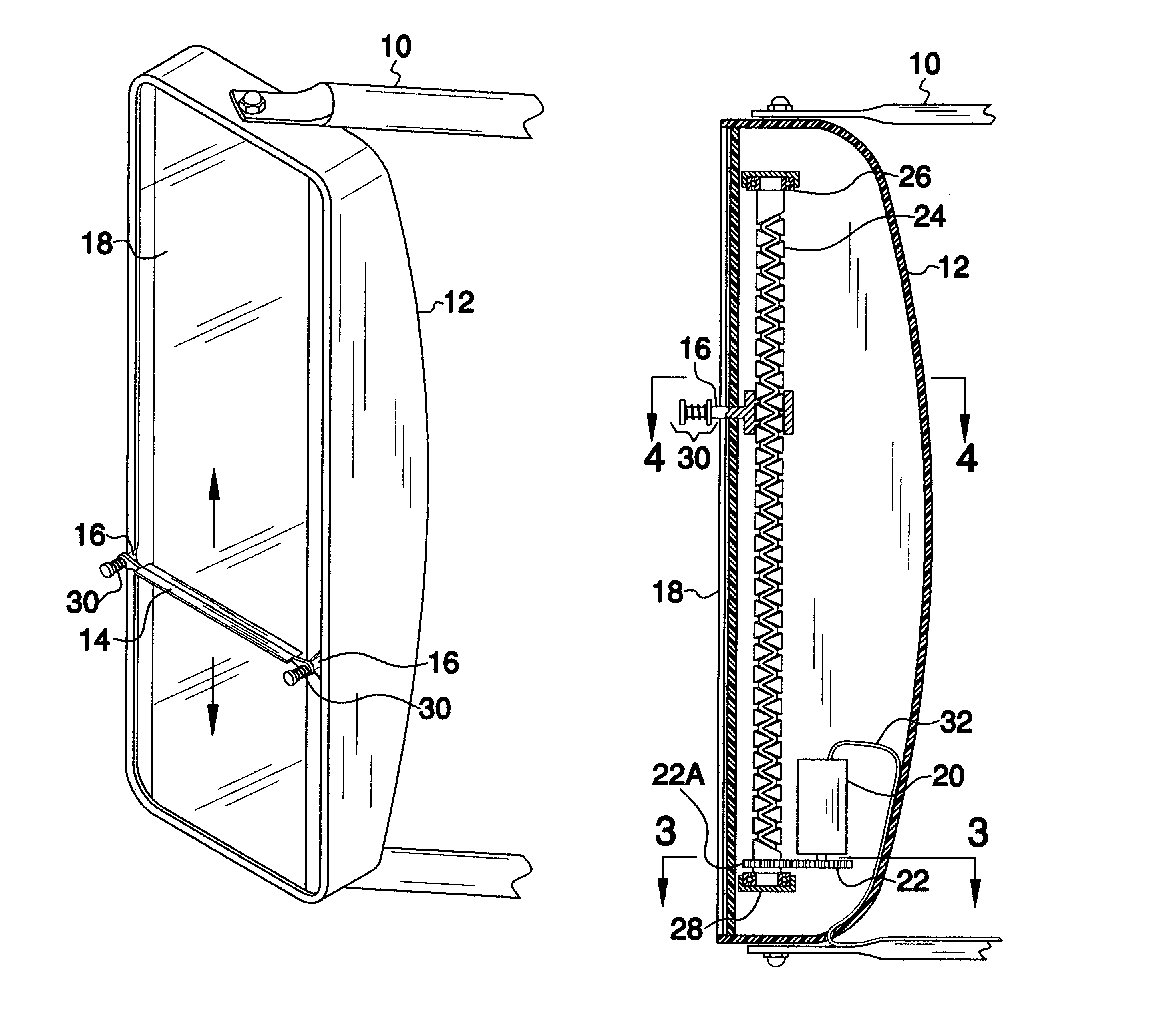
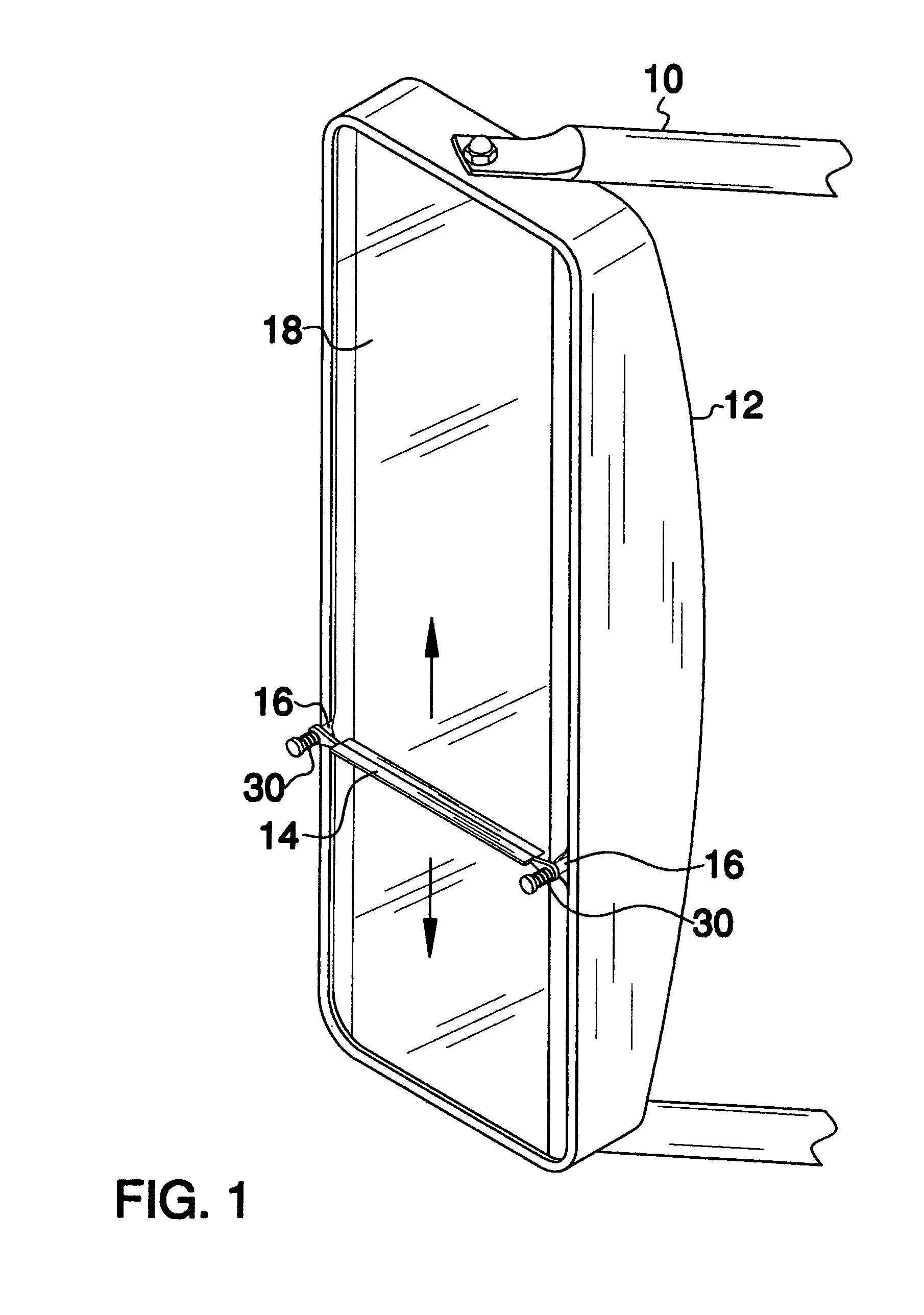
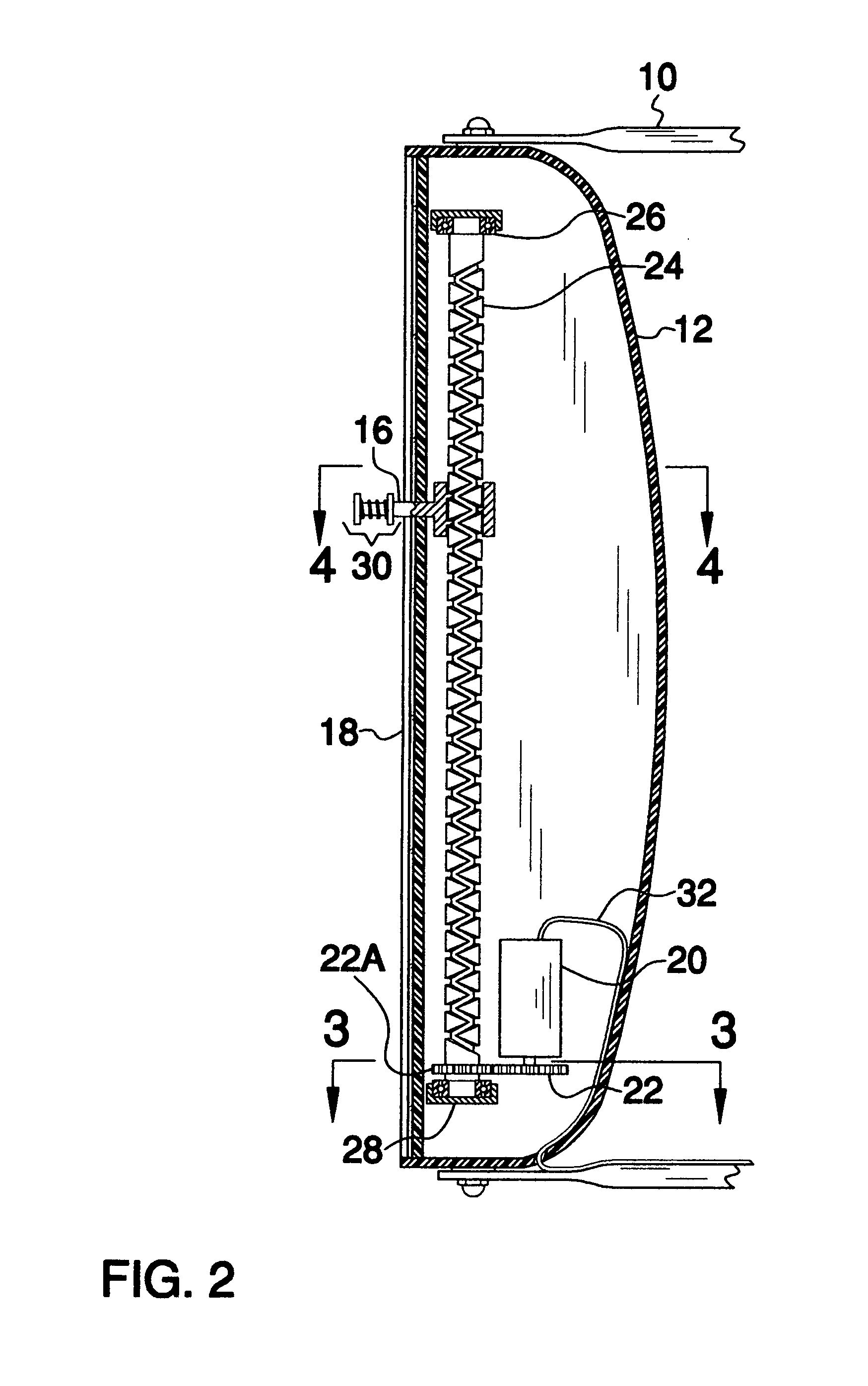
[0034]FIG. 1 shows an extern...


PUM


Abstract

In one aspect, the invention relates a rearview mirror wiper system suitable for use on, for example, large tractor-trailer trucks, delivery trucks, vans, motor homes, cars and other motor vehicles. The rearview wiper system of the present invention has many advantages over prior art systems. It ensures an even and adjustable pressure over the entire wiping surface, has a minimum of parts exposed to the elements so that it is less susceptible to icing and is easy for the user to maintain.

Description

BACKGROUND OF INVENTION[0001]Operating vehicles in inclement weather is difficult and many devices have been developed to aid drivers. For example, cars and trucks (not to mention boats, airplanes and trains) have windshield wipers to clear rainwater, snow and other forms of precipitation off of the windshield. Today, many vehicles also have wipers mounted for use on the rear window and mounted for use on headlights. However, wipers for outside rearview mirrors have not become popular even though the safety features of such devices are self-evident. This is because the prior art devices are not without problems of their own.[0002]For example U.S. Pat. No. 6,324,718 to Johnson discloses a side mounted wiper assembly for external rearview mirrors. This device has two major problems. First, the mechanism responsible for moving the wiper across the mirror glass is exposed to the elements. Because of this, the mechanism is prone to corrosion and, in the event of a freezing rain or heavy ...

Claims


Application Information

Patent Timeline
Patent Type & Authority Patents(United States)
IPC IPC(8): B60S1/44B60S1/26B60S1/46B60S1/56B60S1/60
CPCB60S1/3404B60R1/0602
Inventor NEMETH, GLENN
Owner NEMETH GLENN
Why Eureka
Try Eureka