Charging/Powering Device for an Electronic Device and Electronic Device Incorporating Same

a charging/powering device and electronic device technology, applied in the field of electronic devices, can solve the problems of limiting the movement capabilities of the mouse, cordless mouse suffers from its own disadvantage, and problems such as problems, and achieves the effects of less prone to mechanical failure, simple design, and low manufacturing cos

Inactive Publication Date: 2010-03-11
NACSON SABATINO
View PDF6 Cites 21 Cited by
  • Summary
  • Abstract
  • Description
  • Claims
  • Application Information

AI Technical Summary

Benefits of technology

[0018]The present invention provides advantages in that since the charging / powering device is of a simple design, it can to be manufactured inexpensively and is less prone to mechanical failure. The design of the charging / powering device also allows it to be incorporated into electronic devices inexpensively. When the charging / powering device is incorporated into an electronic device such as for example a computer-pointing device, cellular telephone, PDA, BlackBerry®, hand-held gaming unit etc., the electronic device has an extended operating time as compared to conventional electronic devices due to the fact that movement of the rotatable element(s) of the electronic device is converted into electrical power. This enables the electronic device to be continually powered through rotation of the rotatable element(s).

Problems solved by technology

Although this type of mouse is satisfactory for the most part, problems do exist.
Since the mouse is physically connected to the computer by the cord, the cord restricts the movement capabilities of the mouse.
However, the cordless mouse suffers from its own disadvantage.
Since the cordless mouse is not physically connected to the computer, the cordless mouse is not able to draw power from the computer power supply.
Batteries of course require replacing when they run low and as will be appreciated, replacing batteries is inconvenient.
Also, batteries can drain at unexpected and inappropriate times creating user annoyance, especially if the batteries drain while the user is in the middle of an important project.
The disadvantages associated with the cordless mouse discussed above are of course not limited to cordless mice.

Method used


Image

  • Charging/Powering Device for an Electronic Device and Electronic Device Incorporating Same
  • Charging/Powering Device for an Electronic Device and Electronic Device Incorporating Same
  • Charging/Powering Device for an Electronic Device and Electronic Device Incorporating Same

Examples


Embodiment Construction

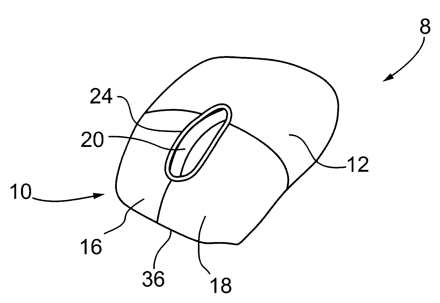
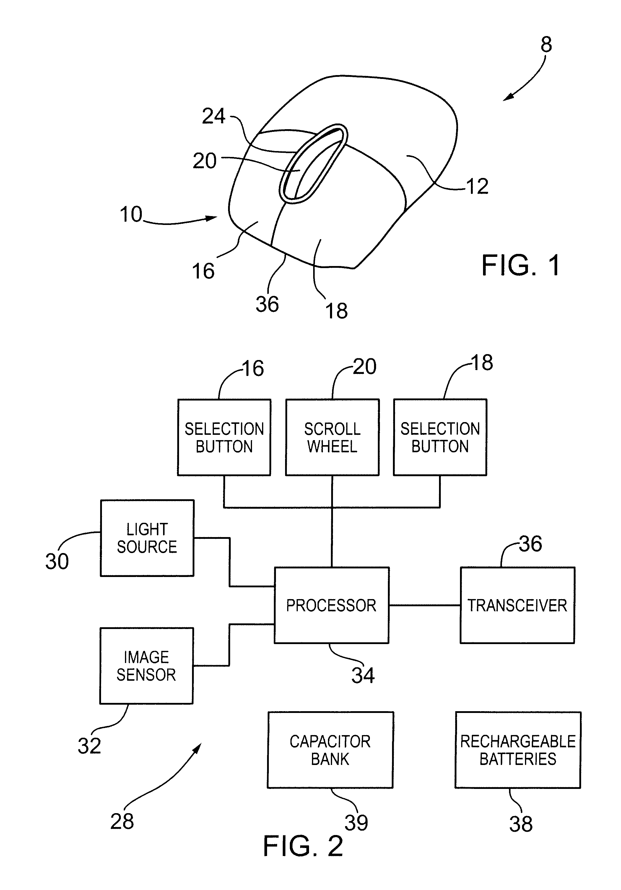
[0031]Turning now to FIG. 1, a computer-pointing device in the form of a cordless mouse is shown and is generally identified by reference numeral 8. The cordless mouse 8 includes a generally ovate, smoothly contoured housing 10. A pair of buttons 16 and 18 is provided on the upper surface 12 of the housing 10 near its front end. A scroll wheel 20 protrudes through an opening in the upper surface 12 of the housing 10. In this embodiment, the scroll wheel 20 is positioned between the two buttons 16 and 18 within a well 24 formed in the upper surface 12. The housing 10 is ergonomically shaped so that the hand of a user may fit comfortably around the mouse 8 while allowing the user to interact with the buttons 16 and 18 and the scroll wheel 20.

[0032]The mouse 8 in this embodiment is an optical mouse and accordingly, the interior of the housing 10 accommodates a circuit board on which the optoelectronics of the mouse 8 are mounted. As is well known and shown in FIG. 2, the optoelectronic...


PUM


Abstract

A charging / powering device comprises at least one manually rotatable element, a power generating mechanism coupled to the at least one rotatable element, the power generating mechanism converting rotational movement of said at least one rotatable element into electrical energy and an energy harvesting module collecting and storing the electrical energy generated by the power generating mechanism, the energy harvesting module further being operable to output stored electrical energy.

Description

CROSS-REFERENCE TO RELATED APPLICATIONS[0001]This application claims the benefit of U.S. Provisional Application Ser. No. 61 / 064,503 filed on Mar. 10, 2008 for an invention entitled “Self-Powered Computer-Pointing Device”.FIELD OF THE INVENTION[0002]The present invention relates generally to electronic devices and more specifically, to a charging / powering device for an electronic device and to an electronic device incorporating same.BACKGROUND OF THE INVENTION[0003]Computer-pointing devices are often used in connection with computers to facilitate user interaction with application programs and to enhance the functionality of the computers. One common type of computer-pointing device is the cord-based mouse. This type of mouse is connected to the computer by a cord and is moved over a pad or other suitable surface to effect movement of the cursor displayed on the monitor of the computer. When the cursor is positioned at the desired location, actions can be invoked by clicking on one ...

Claims


Application Information

Patent Timeline
Patent Type & Authority Applications(United States)
IPC IPC(8): H02J7/00H02K11/00H02K7/10
CPCG06F1/26G06F3/03543Y02B40/90H02K7/1853H02J7/32Y02B40/00
Inventor NACSON, SABATINO
Owner NACSON SABATINO
Why Eureka
Try Eureka