Fixed rate egr system

a technology of egr and cylinders, which is applied in the direction of electrical control, machines/engines, mechanical equipment, etc., can solve the problems of reducing the production of nox, reducing the amount of egr required, and long transport delay of the lp-egr circuit, so as to reduce the loss of throttling, improve vehicle emissions and fuel economy, and maintain the desirable combustion stability of the engin

Inactive Publication Date: 2012-02-02
FORD GLOBAL TECH LLC
View PDF18 Cites 90 Cited by
  • Summary
  • Abstract
  • Description
  • Claims
  • Application Information

AI Technical Summary

Benefits of technology

[0002]Exhaust gas recirculation (EGR) systems divert a portion of the exhaust gases back to the intake to cool combustion temperatures and reduce throttling losses, thus improving vehicle emissions and fuel economy. In turbocharged engines, an EGR system may include a low-pressure EGR (LP-EGR) circuit, a high-pressure EGR (HP-EGR) circuit, or both. The LP-EGR circuit diverts exhaust gases after the gases pass through the turbine of the turbocharger and injects the gases before the compressor, while the HP-EGR circuit diverts exhaust gases before the turbine and injects the gases after the intake throttle. Traditionally, the amount of LP-EGR and / or HP-EGR routed through the EGR system is measured and adjusted based on engine speed and load during engine operation to maintain desirable combustion stability of the engine while providing emissions and fuel economy benefits.
[0006]The present description may provide several advantages. Because transient control issues may reduce the areas of the speed-load map under which EGR may be utilized effectively, improving transient control may extend the use of EGR under more operating conditions, reducing throttling losses and improving fuel economy. Further, EGR lowers peak cylinder temperatures, reducing the production of NOx. Thus, extending the use of EGR into more areas of the speed-load map may reduce engine-out emissions. Also, operating the LP-EGR circuit with a fixed percentage rate of fresh airflow may improve component durability. For example, not turning LP-EGR on and off during tip-outs and tip-ins reduces the number of thermal cycles on the EGR cooler, improving its durability. Additionally, the number of closing events of the EGR valve may be reduced, improving valve durability. Next, EGR mixing may be improved, as running a consistent LP-EGR amount can allow for optimized sizing of the EGR and air flow ducts to create even dispersion of the EGR into the air. Finally, running fixed LP-EGR may reduce the dynamic range requirements for the EGR valve and sensors and simplify the control strategy for the EGR throttle, reducing system costs and complexity.

Problems solved by technology

However, the inventors herein have recognized an issue with the above approach.
The LP-EGR circuit has a long transport delay, as the exhaust gases must travel through the turbo compressor, high pressure air induction plumbing, charge air cooler, and intake manifold before reaching the combustion chamber.
As a result, it may be difficult to provide the desired amount of EGR to the cylinders, particularly during transient conditions.
Further, EGR lowers peak cylinder temperatures, reducing the production of NOx.

Method used


Image

  • Fixed rate egr system
  • Fixed rate egr system
  • Fixed rate egr system

Examples


Embodiment Construction

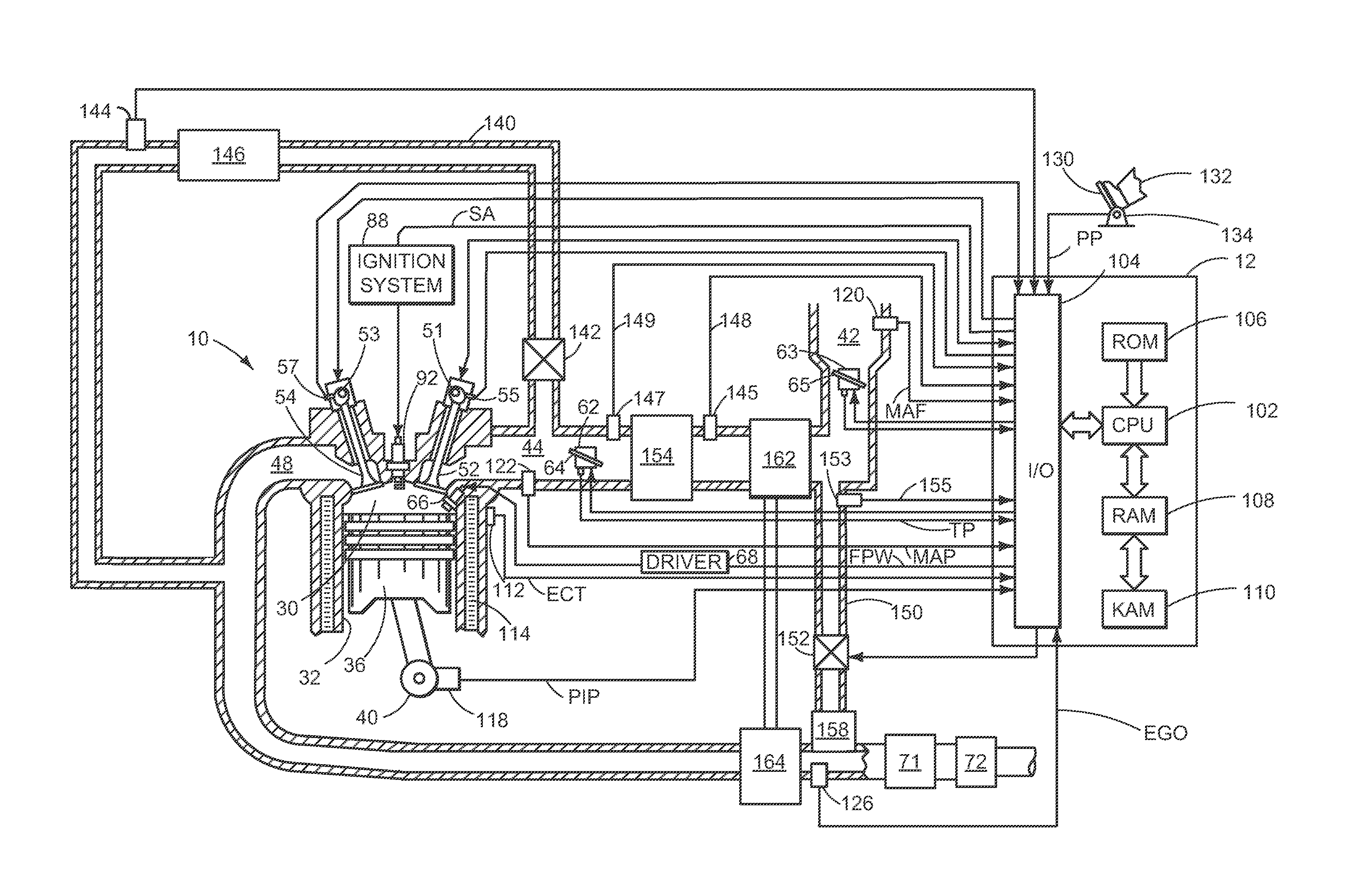
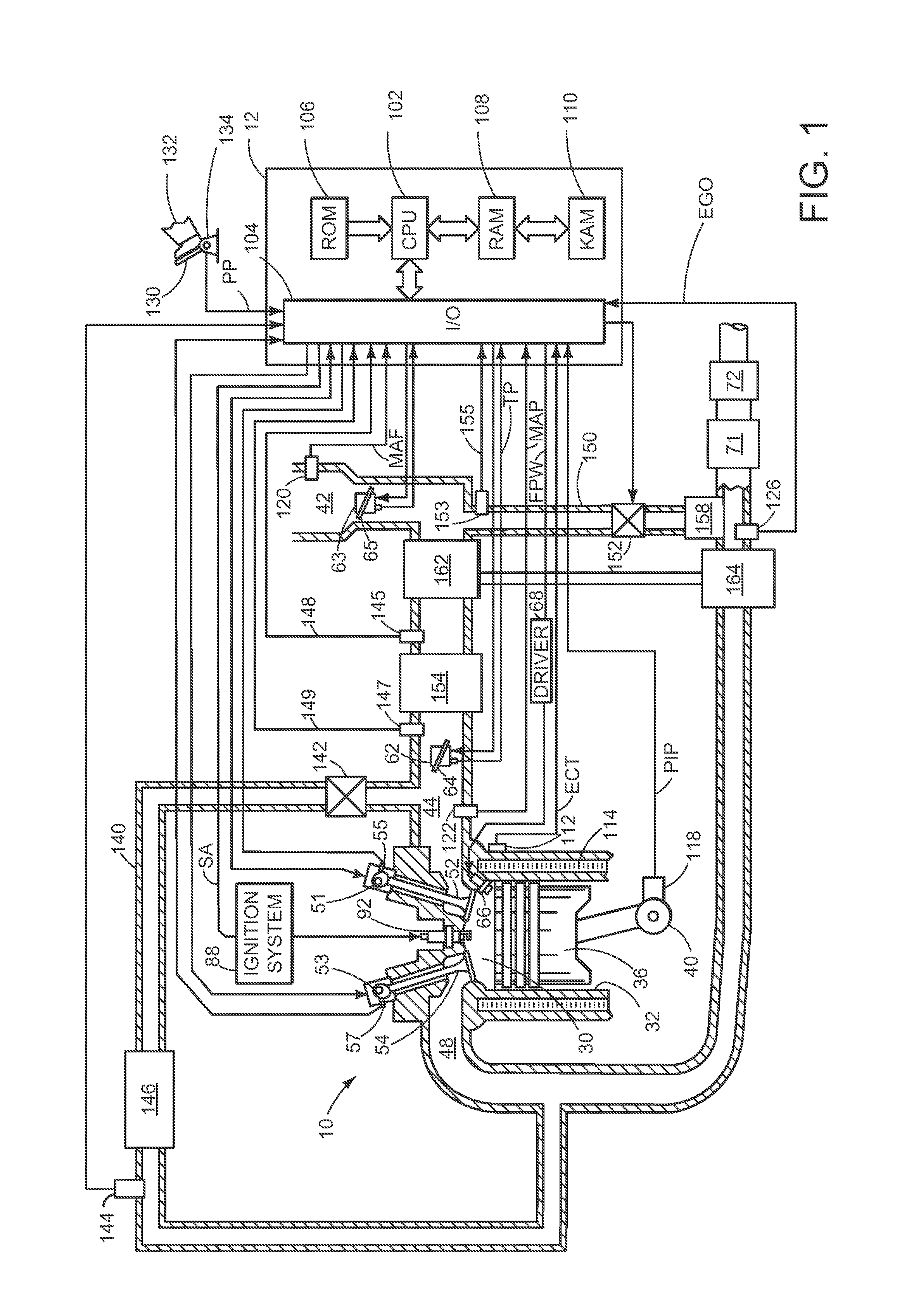
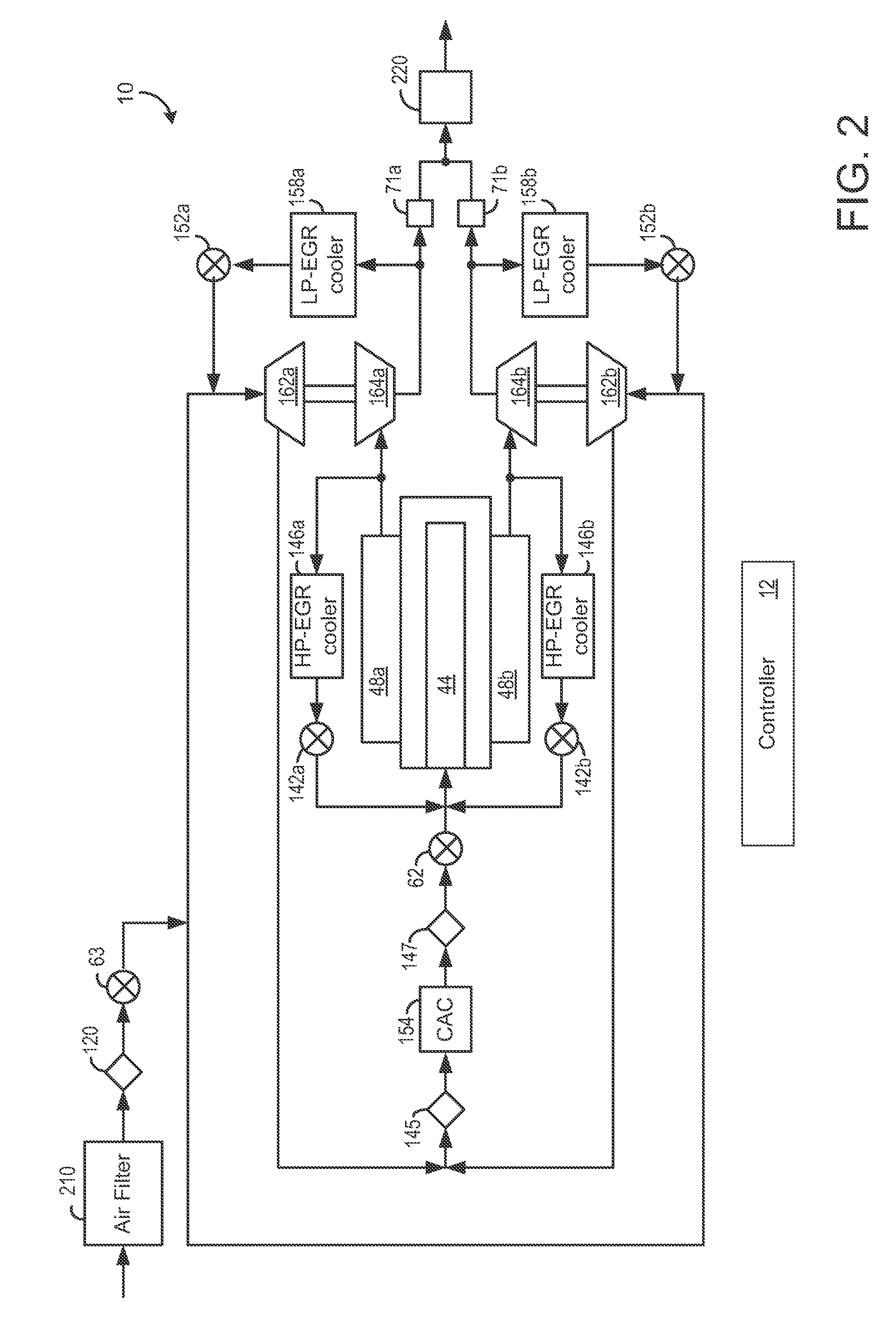
[0016]The present description relates to an EGR system coupled to a turbocharged engine in a motor vehicle. In one non-limiting example, the engine may be configured as part of the system illustrated in FIG. 1, wherein the engine includes at least one cylinder, a control system, a turbocharger, and an exhaust gas recirculation system, among other features. The engine may be configured with a plurality of cylinder banks as illustrated in FIG. 2. The systems of FIGS. 1 and 2 may be operated with a method such as the examples illustrated in FIGS. 3-6. The various EGR operating modes may be determined by engine-speed load maps, such as one depicted in FIG. 7. FIGS. 8A and 8B illustrate various engine operating parameters during execution of the methods of FIGS. 3-6.

[0017]Referring now to FIG. 1, it shows a schematic diagram of one cylinder of multi-cylinder engine 10, which may be included in a propulsion system of an automobile, is shown. Engine 10 may be controlled at least partially ...


PUM


Abstract

A method is provided for controlling EGR flow in turbocharged engine. The method comprises operating a low-pressure exhaust gas recirculation (LP-EGR) system at a fixed EGR percentage rate of fresh airflow from mid-load down to a minimum engine load, even as load changes. In this way, errors in the delivered LP-EGR rate during transient conditions may be alleviated by providing a fixed EGR percentage of fresh airflow at all engine loads within a fixed mode range.

Description

FIELD[0001]The present application relates to control of an exhaust gas recirculation system in a motor vehicle.BACKGROUND AND SUMMARY[0002]Exhaust gas recirculation (EGR) systems divert a portion of the exhaust gases back to the intake to cool combustion temperatures and reduce throttling losses, thus improving vehicle emissions and fuel economy. In turbocharged engines, an EGR system may include a low-pressure EGR (LP-EGR) circuit, a high-pressure EGR (HP-EGR) circuit, or both. The LP-EGR circuit diverts exhaust gases after the gases pass through the turbine of the turbocharger and injects the gases before the compressor, while the HP-EGR circuit diverts exhaust gases before the turbine and injects the gases after the intake throttle. Traditionally, the amount of LP-EGR and / or HP-EGR routed through the EGR system is measured and adjusted based on engine speed and load during engine operation to maintain desirable combustion stability of the engine while providing emissions and fue...

Claims


Application Information

Patent Timeline
Patent Type & Authority Applications(United States)
IPC IPC(8): F02B33/44
CPCF02B29/0406Y02T10/47F02D9/02F02D41/005F02D41/0065F02D41/0077F02D2041/0017F02M25/0707F02M25/0709F02M25/0711F02M25/0731F02M25/0732F02M25/0744F02M25/0748F02B37/007F02M26/05F02M26/06F02M26/08F02M26/28F02M26/24F02M26/38F02M26/42Y02T10/40F02D41/0005
Inventor STYLES, DANIEL JOSEPHHILDITCH, JAMESRUONA, WILLIAM CHARLES
Owner FORD GLOBAL TECH LLC
Why Eureka
Try Eureka