Exhaust gas recirculation (EGR) system

a technology of exhaust gas and recirculation system, which is applied in the direction of mechanical equipment, machines/engines, electric control, etc., can solve the problems of high exhaust temperature, condensation, exhaust pulsation, etc., and achieve the effect of reducing emissions, maintaining desirable combustion stability of the engine, and improving fuel economy

Active Publication Date: 2013-12-31
FORD GLOBAL TECH LLC
View PDF18 Cites 8 Cited by
  • Summary
  • Abstract
  • Description
  • Claims
  • Application Information

AI Technical Summary

Benefits of technology

[0002]It may be desirable for an engine to include a turbocharger and exhaust gas recirculation (EGR) to reduce emissions of NOX, CO, and other gasses and to improve fuel economy. An EGR system may include a low pressure exhaust gas recirculation (LP-EGR) system, a high pressure exhaust gas recirculation (HP-EGR) system, or both a LP-EGR and a HP-EGR system, for example. The amount of EGR routed through the EGR system is measured and adjusted during engine operation to maintain desirable combustion stability of the engine. One solution for measuring the amount of EGR in the LP-EGR system is for the LP-EGR system to include a mass air flow (MAF) sensor downstream of the hot, moist, exhaust gasses and upstream of the turbocharger compressor. However, the MAF sensor may be exposed to high exhaust temperatures, high concentrations of soot and exhaust hydrocarbons, water condensation, and exhaust pulsations. These conditions may reduce the lifetime of the MAF sensor and reduce its accuracy when measuring the EGR rate. Additionally, a dual bank engine may include two MAF sensors, increasing the engine's cost.
[0004]In one example, a method for controlling an engine is disclosed. Low-pressure EGR is delivered downstream of an intake throttle and upstream of a turbocharger compressor. Further, an operating parameter is adjusted based on an EGR mass flow identified from a difference between a measured clean air mass flow entering the intake throttle and a total mass flow measured downstream from the turbocharger compressor. In this manner, the EGR rate may be measured and maintained at a desirable level while a MAF sensor may be exposed to lower temperatures, lower concentrations of soot and exhaust hydrocarbons, less water condensation, and fewer exhaust pulsations. Thus, the MAF sensor may potentially have a longer lifetime and greater accuracy.

Problems solved by technology

However, the MAF sensor may be exposed to high exhaust temperatures, high concentrations of soot and exhaust hydrocarbons, water condensation, and exhaust pulsations.
These conditions may reduce the lifetime of the MAF sensor and reduce its accuracy when measuring the EGR rate.
Additionally, a dual bank engine may include two MAF sensors, increasing the engine's cost.
Thus, the MAF sensor may potentially have a longer lifetime and greater accuracy.

Method used


Image

  • Exhaust gas recirculation (EGR) system
  • Exhaust gas recirculation (EGR) system
  • Exhaust gas recirculation (EGR) system

Examples


Embodiment Construction

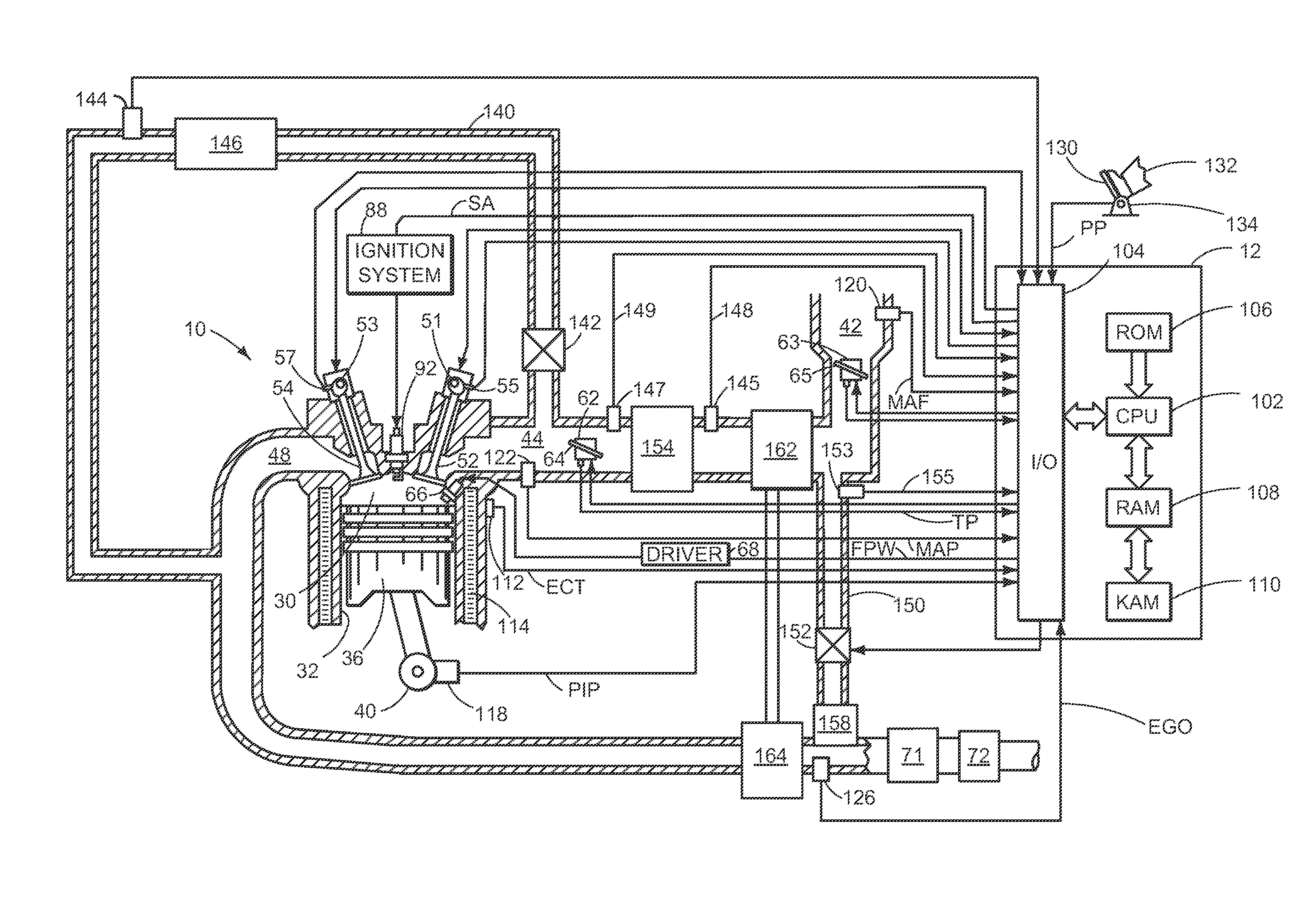
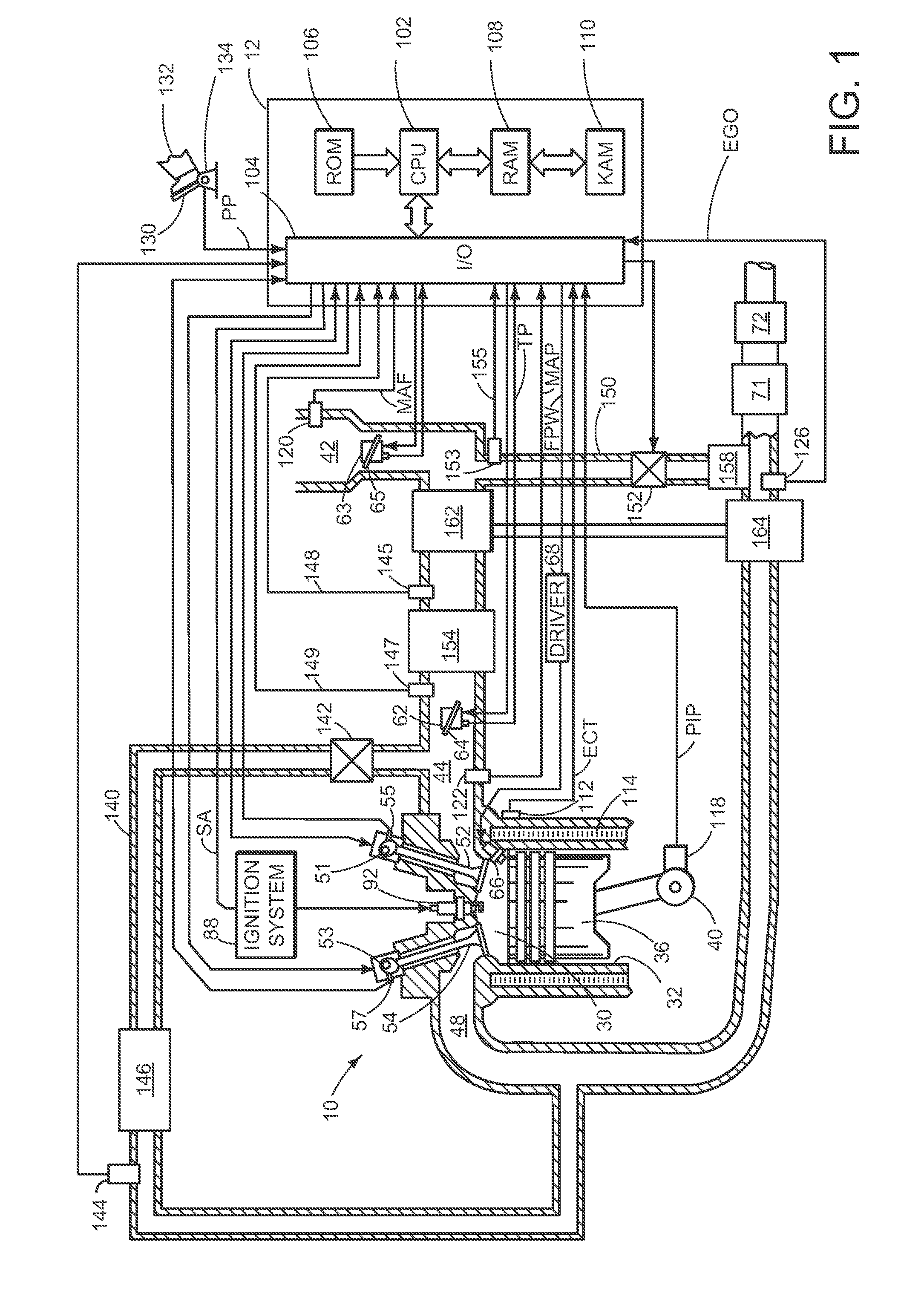
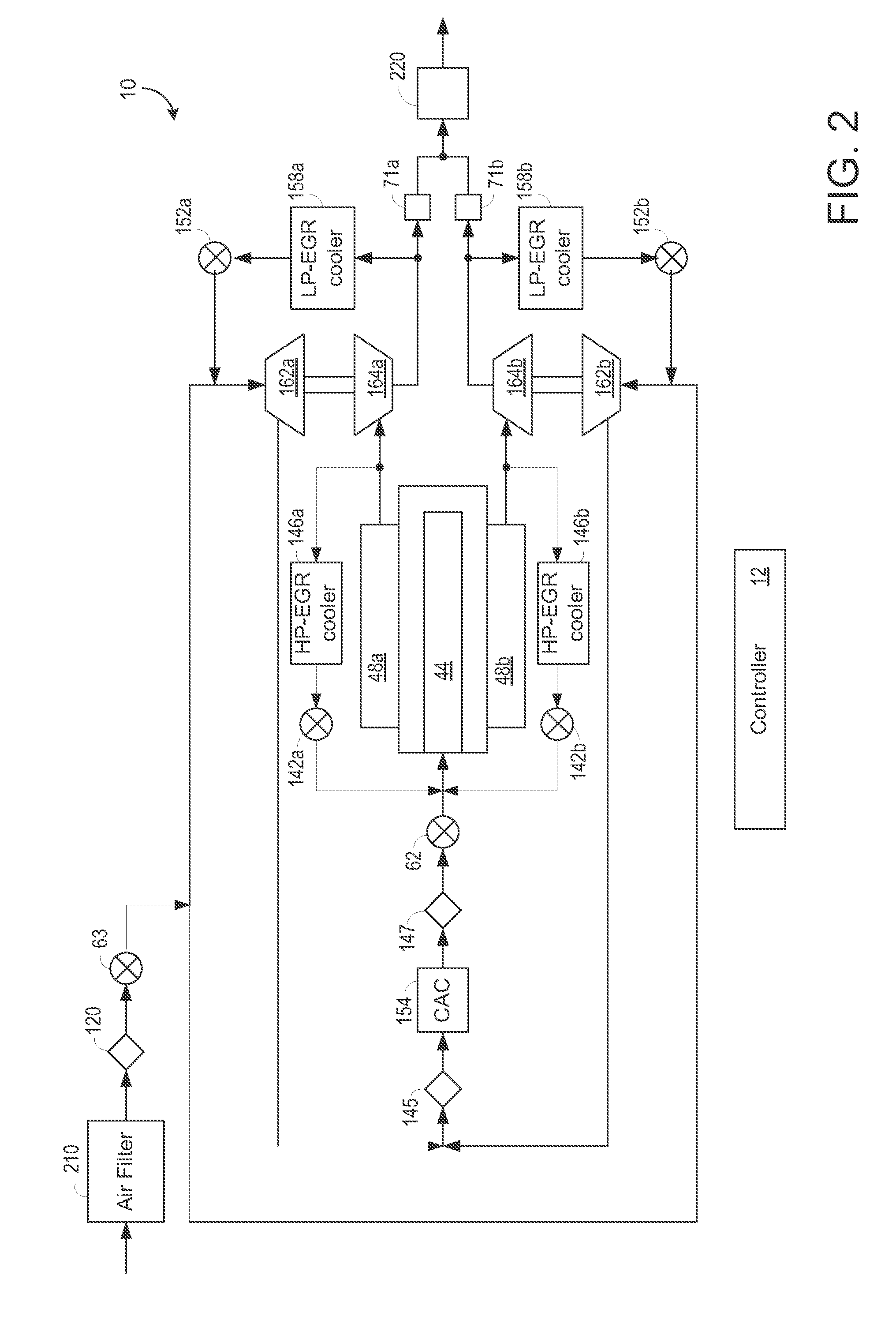
[0010]The present description relates to an EGR system coupled to a turbocharged engine in a motor vehicle. In one non-limiting example, the engine may be configured as part of the system illustrated in FIG. 1, wherein the engine includes a turbocharger compressor, an intake throttle upstream of the turbocharger compressor, an intake manifold downstream of the turbocharger compressor, and an EGR system delivering EGR downstream of the intake throttle and upstream of the compressor. The engine may be configured with a plurality of cylinder banks as illustrated in FIG. 2. The systems of FIGS. 1 and 2 may be operated with a method such as the example illustrated in FIG. 3. For example, the method may comprise measuring clean air mass flow entering the intake throttle and measuring a total mass flow downstream from the turbocharger compressor and upstream of the intake manifold. The EGR mass flow may be calculated by subtracting the difference between the total mass flow and the clean a...


PUM


Abstract

Various systems and methods are described for an exhaust gas recirculation (EGR) system coupled to an engine in a vehicle. One example method comprises, calculating an EGR mass flow from a difference between measurements of clean air mass flow and total mass flow, and correcting for a transient mass flow error.

Description

TECHNICAL FIELD[0001]The present application relates generally to an exhaust gas recirculation system coupled to an engine in a motor vehicle.BACKGROUND AND SUMMARY[0002]It may be desirable for an engine to include a turbocharger and exhaust gas recirculation (EGR) to reduce emissions of NOX, CO, and other gasses and to improve fuel economy. An EGR system may include a low pressure exhaust gas recirculation (LP-EGR) system, a high pressure exhaust gas recirculation (HP-EGR) system, or both a LP-EGR and a HP-EGR system, for example. The amount of EGR routed through the EGR system is measured and adjusted during engine operation to maintain desirable combustion stability of the engine. One solution for measuring the amount of EGR in the LP-EGR system is for the LP-EGR system to include a mass air flow (MAF) sensor downstream of the hot, moist, exhaust gasses and upstream of the turbocharger compressor. However, the MAF sensor may be exposed to high exhaust temperatures, high concentra...

Claims


Application Information

Patent Timeline
Patent Type & Authority Patents(United States)
IPC IPC(8): F02B37/007F02M25/07
CPCF02M25/0711Y02T10/121F02B37/007F02M25/0707F02M26/05F02M26/08F02D41/222F02D41/18F02D41/2474F02D21/08F02D23/00
Inventor SURNILLA, GOPICHANDRASTYLES, DANIEL JOSEPHJANKOVIC, MRDJAN J.BUCKLAND, JULIA HELENKARNIK, AMEY Y.
Owner FORD GLOBAL TECH LLC
Why Eureka
Try Eureka