Method and system for knock control

a technology of engine knock and control system, applied in the direction of electric control, ignition automatic control, machines/engines, etc., can solve the problems of excessive engine knock or pre-ignition, inefficient use of spark retard or combustion mixture enrichment, and inability to deliver egr (0% egr) , to achieve the effect of reducing throttling losses, reducing vehicle emissions and fuel economy, and maintaining desirable combustion stability of engines

Active Publication Date: 2016-03-15
FORD GLOBAL TECH LLC
View PDF13 Cites 12 Cited by
  • Summary
  • Abstract
  • Description
  • Claims
  • Application Information

AI Technical Summary

Benefits of technology

[0002]Exhaust gas recirculation (EGR) systems divert a portion of the exhaust gases back to the intake to cool combustion temperatures and reduce throttling losses, thus improving vehicle emissions and fuel economy. In turbocharged engines, an EGR system may include a cooled low-pressure EGR (LP-EGR) circuit wherein exhaust gases are diverted after the gases pass through the turbine of the turbocharger and injected before the compressor upon passage through an EGR cooler. The amount of LP-EGR routed through the EGR system is measured and adjusted based on engine speed and load during engine operation to maintain desirable combustion stability of the engine while providing emissions and fuel economy benefits.
[0003]One example EGR system is shown by Styles et al. in US 20120023937. Therein, LP-EGR is provided at a fixed EGR percentage rate of fresh airflow over a large area of an engine map, including from mid-load down to minimum engine load, even as engine load changes. At higher engine loads, the EGR percentage rate is varied based on engine operating conditions. In addition, at very low engine loads and / or engine idle conditions, no EGR (0% EGR) may be delivered. Such an approach improves transient control and extends the use of EGR over a wider range of operating conditions.
[0005]In one example, some of the above issues can be at least partly addressed by a method for an engine comprising: in response to increasing load while operating with lower EGR, increasing EGR, and fueling the engine with split fuel injection per cycle until EGR is higher than a threshold. In this way, knock and pre-ignition during transient tip-ins can be better mitigated.
[0007]In this way, split fuel injection may be temporarily used while LP-EGR is ramped in to reduce abnormal combustion events. By using at least a lean intake stroke injection and a rich compression stroke injection around the time of spark, the likelihood of knock and pre-ignition can be reduced while maintaining combustion air-fuel ratio at stoichiometry. By delaying the need for spark retard or enrichment in addressing knock or pre-ignition, significant improvements in fuel economy are achieved.

Problems solved by technology

In addition, at very low engine loads and / or engine idle conditions, no EGR (0% EGR) may be delivered.
However the inventors herein have identified a potential issue with such an approach.
Herein, the engine may enter the high load operating region fast enough that the transport delay of EGR filling the intake system can delay EGR entering the combustion chamber in sufficient concentration to provide the required knock mitigation.
As a result, excessive engine knock or pre-ignition can occur.
To mitigate the knock or pre-ignition, inefficient use of spark retard or combustion mixture enrichment may be required degrading fuel economy, and offsetting the fuel economy benefits of the prior EGR usage.
The abnormal combustion events can also erode drive cycle fuel efficiency and potentially damage the engine.
If there is a transport delay in the delivery of the desired engine dilution, the engine may become knock-limited.

Method used


Image

  • Method and system for knock control
  • Method and system for knock control
  • Method and system for knock control

Examples


Embodiment Construction

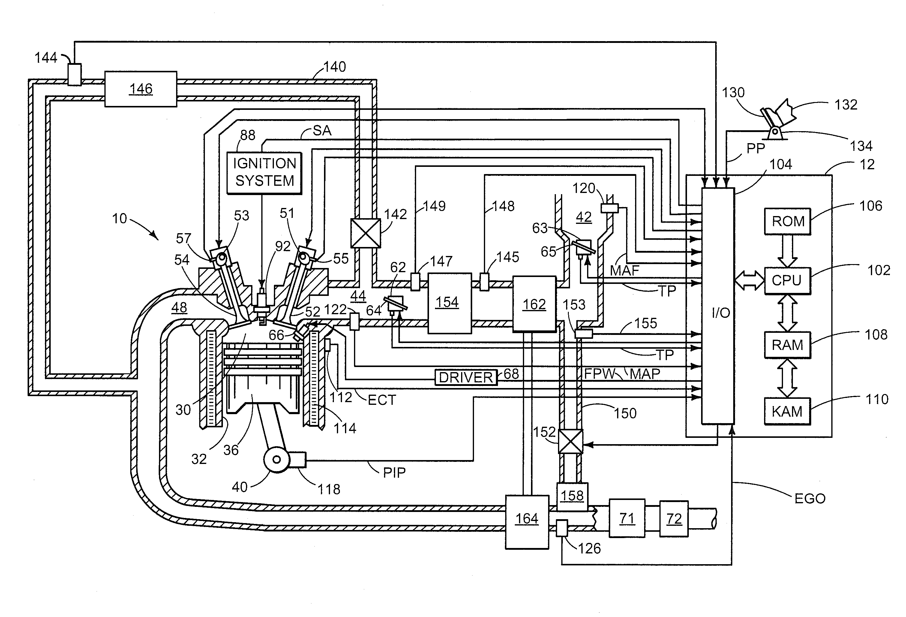
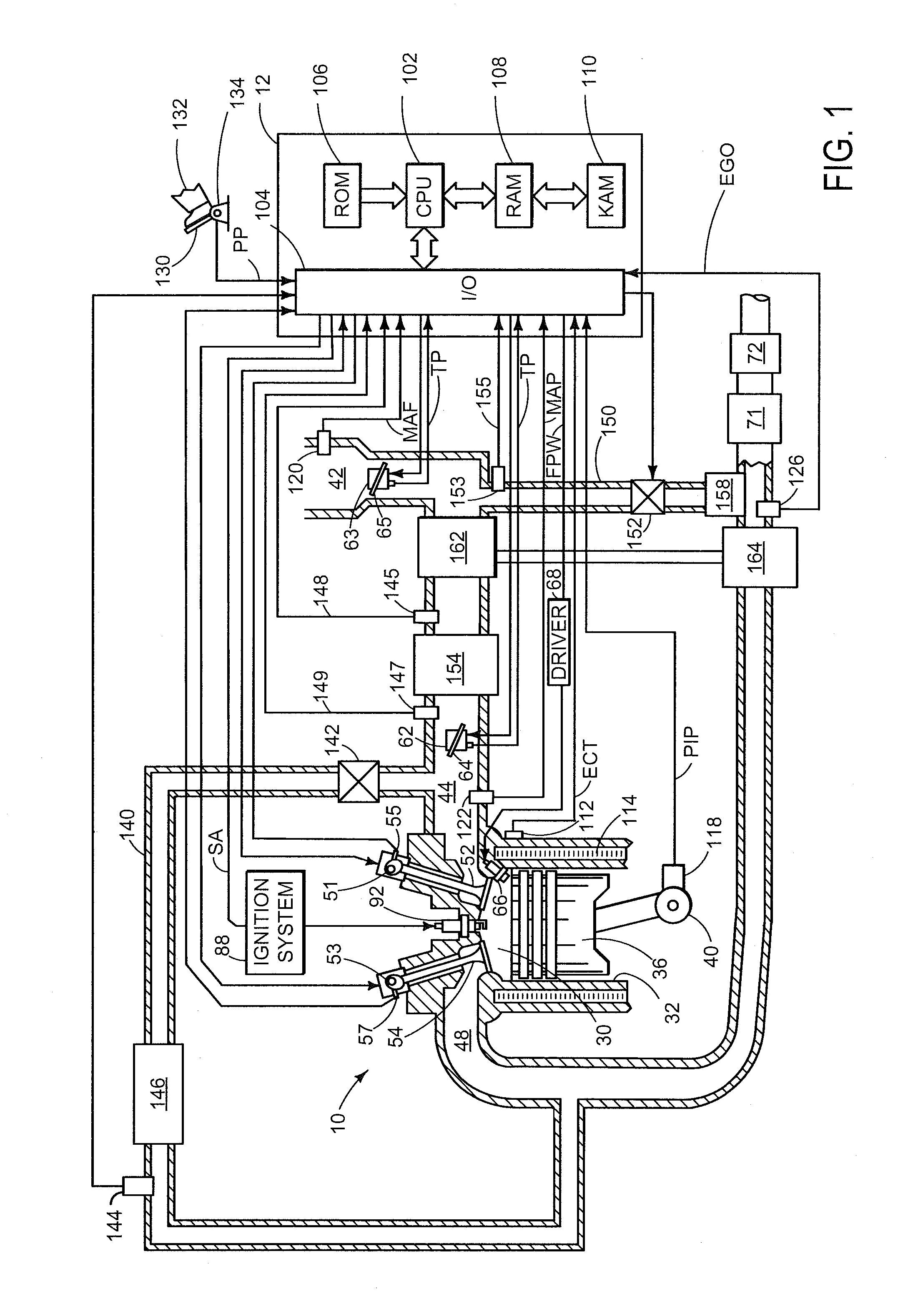
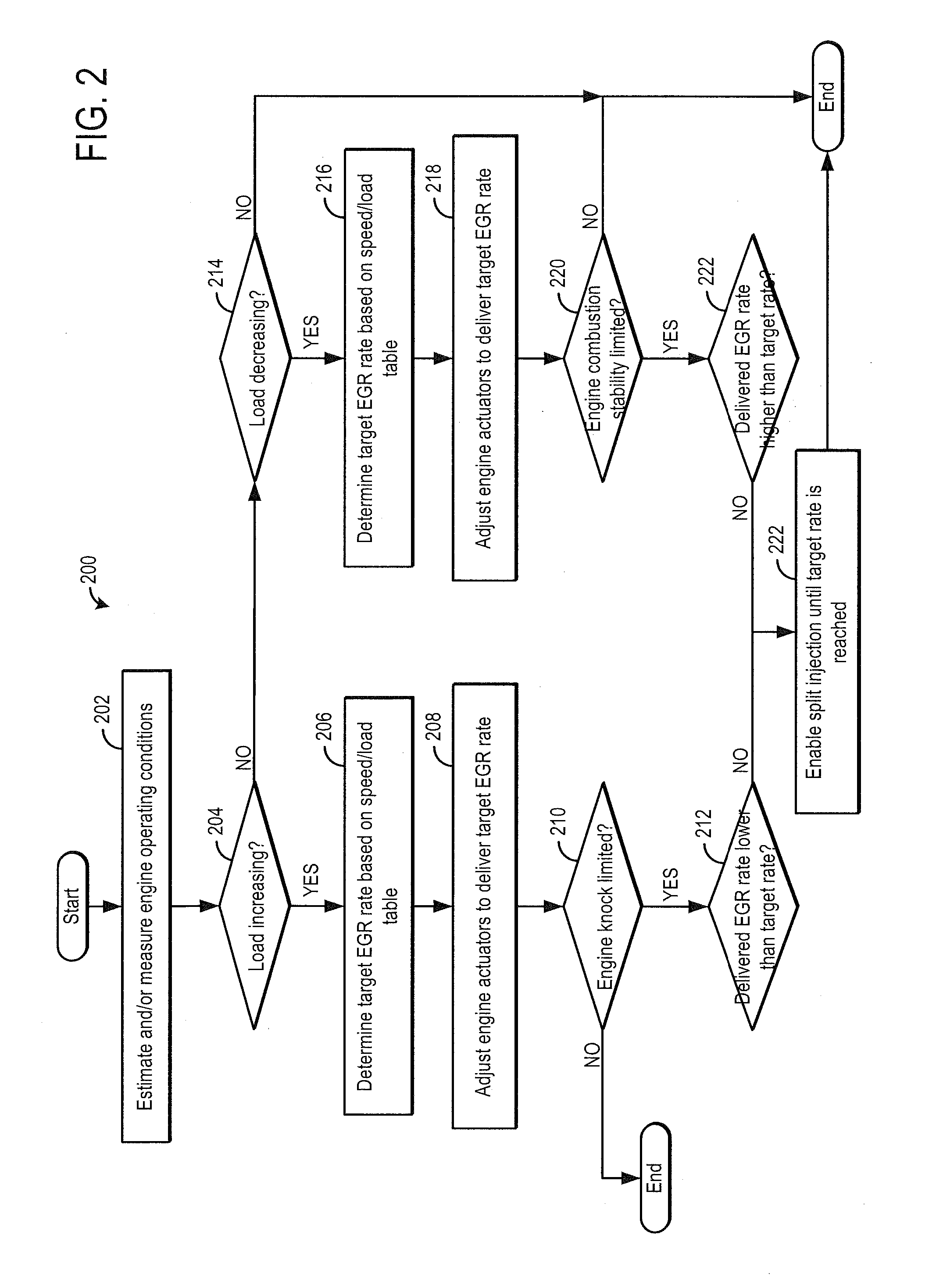
[0018]The present description relates to an EGR system coupled to a turbocharged engine in a motor vehicle. In one non-limiting example, the engine may be configured as part of the system illustrated in FIG. 1, wherein the engine includes at least one cylinder, a control system, a turbocharger, and an exhaust gas recirculation system, among other features. An engine controller may be configured to perform a control routine, such as the routine of FIGS. 2-4, to transiently shift to split fuel injection while ramping in LP-EGR to mitigate knock issues arising from delayed EGR delivery and transiently shift to split fuel injection while ramping out LP-EGR to improve engine dilution tolerance. The split fuel injection may include at least an intake stroke injection and a compression stroke injection, as depicted at FIGS. 5-7. Example engine adjustments during the ramping in or ramping out of the LP-EGR are shown at FIGS. 8 and 10. In this way, engine operation with EGR can be improved.

[...


PUM


Abstract

Methods and systems are provided for improving engine knock tolerance, in particular when rapidly ramping in LP-EGR from low levels of EGR. Until a desired LP-EGR rate is achieved, fuel may be delivered as a split injection with at least an intake stroke injection and a compression stroke injection to compensate for the transport delay in EGR filling the intake system. Subsequently, single fuel injection may be resumed.

Description

FIELD[0001]The present application relates to methods and systems for improving engine knock tolerance in a motor vehicle.BACKGROUND AND SUMMARY[0002]Exhaust gas recirculation (EGR) systems divert a portion of the exhaust gases back to the intake to cool combustion temperatures and reduce throttling losses, thus improving vehicle emissions and fuel economy. In turbocharged engines, an EGR system may include a cooled low-pressure EGR (LP-EGR) circuit wherein exhaust gases are diverted after the gases pass through the turbine of the turbocharger and injected before the compressor upon passage through an EGR cooler. The amount of LP-EGR routed through the EGR system is measured and adjusted based on engine speed and load during engine operation to maintain desirable combustion stability of the engine while providing emissions and fuel economy benefits.[0003]One example EGR system is shown by Styles et al. in US 20120023937. Therein, LP-EGR is provided at a fixed EGR percentage rate of ...

Claims


Application Information

Patent Timeline
Patent Type & Authority Patents(United States)
IPC IPC(8): F02B47/08F02D41/30F02D41/40F02D41/00F02D43/00F02D41/10F02D41/12
CPCF02D43/00F02D41/005F02D41/0072F02D41/3023F02D41/402F02D41/10F02D41/12F02M26/06Y02T10/40F02D41/3076F02P5/145F02B47/08F02D41/0007
Inventor WOOLDRIDGE, STEVENSURNILLA, GOPICHANDRABOYER, BRAD ALANHILDITCH, JAMES ALFREDSHELBY, MICHAEL HOWARDGLUGLA, CHRIS PAULPETERSEN, BENJAMIN RICHARD
Owner FORD GLOBAL TECH LLC
Why Eureka
Try Eureka