Diesel particulate filter passive regeneration during stationary power take-off

a technology of diesel particulate filter and stationary power take-off, which is applied in the direction of electrical control, machines/engines, mechanical equipment, etc., can solve the problems of affecting the formation of no/sub>2/sub>, and achieve the effect of reducing the amount of soot emissions and reducing the amount of trapped particulate matter

Active Publication Date: 2016-03-29
FORD GLOBAL TECH LLC
View PDF7 Cites 0 Cited by
  • Summary
  • Abstract
  • Description
  • Claims
  • Application Information

AI Technical Summary

Benefits of technology

[0002]Emission control devices, such as diesel particulate filters (DPF), may reduce the amount of soot emissions from a diesel engine by trapping soot particles. Such devices may be regenerated during operation of an engine to decrease the amount of trapped particulate matter. Regeneration is typically achieved by raising the temperature of the DPF to a predetermined level, and ensuring that the exhaust gas entering the DPF is of a certain composition.
[0003]Diesel vehicles may further be equipped with exhaust gas recirculation (EGR) systems. EGR systems divert a portion of the exhaust gases back to the intake to cool combustion temperatures and reduce throttling losses, thus improving vehicle emissions and fuel economy. In turbocharged engines, an EGR system may include a low-pressure EGR (LP-EGR) circuit, a high-pressure EGR (HP-EGR) circuit, or both. The LP-EGR circuit diverts exhaust gases after the gases pass through the turbine of the turbocharger and injects the gases before the compressor, while the HP-EGR circuit diverts exhaust gases before the turbine and injects the gases after the intake throttle. Traditionally, the amount of LP-EGR and / or HP-EGR routed through the EGR system is measured and adjusted based on engine speed and load during engine operation to maintain desirable combustion stability of the engine while providing emissions and fuel economy benefits.
[0008]The systems and method described above in the present disclosure allow for regeneration of a diesel particulate filter while a vehicle is in stationary power take-off mode. Described is a method of: during select power take-off conditions, reducing an EGR rate responsive to an indication to regenerate a diesel particulate filter.

Problems solved by technology

Additionally, the formation of NO2 may be affected by modifying the number of injections and the combustion phasing.

Method used


Image

  • Diesel particulate filter passive regeneration during stationary power take-off
  • Diesel particulate filter passive regeneration during stationary power take-off
  • Diesel particulate filter passive regeneration during stationary power take-off

Examples


Embodiment Construction

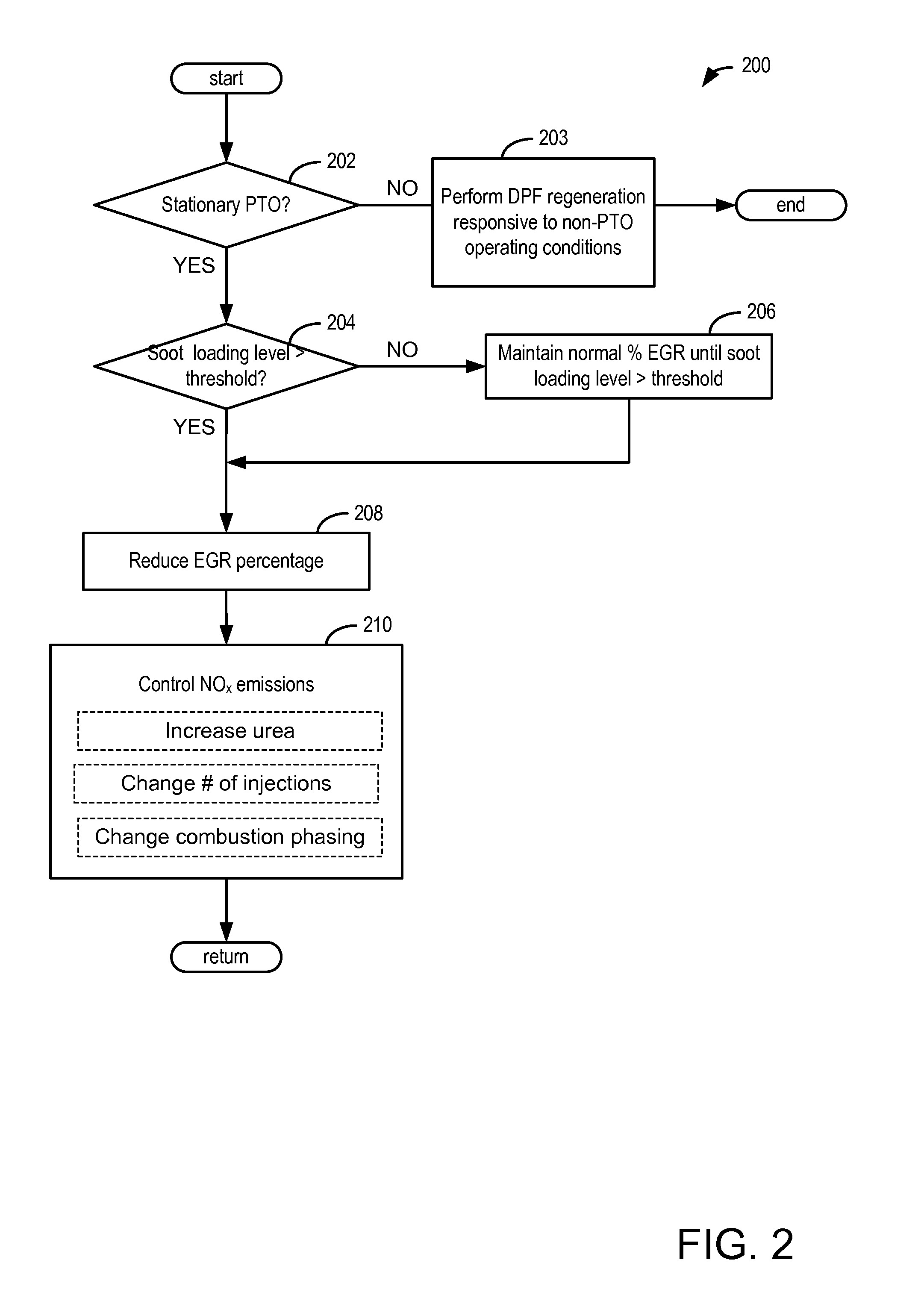
[0014]Soot loading may continue to accumulate during stationary PTO. Below systems and methods are described to regenerate a DPF during stationary PTO. PTO may not be discontinued, and the vehicle may remain stationary through the course of regeneration using the system and method of the present disclosure. The object of the present disclosure is described below with greater detail in reference to the FIGS.

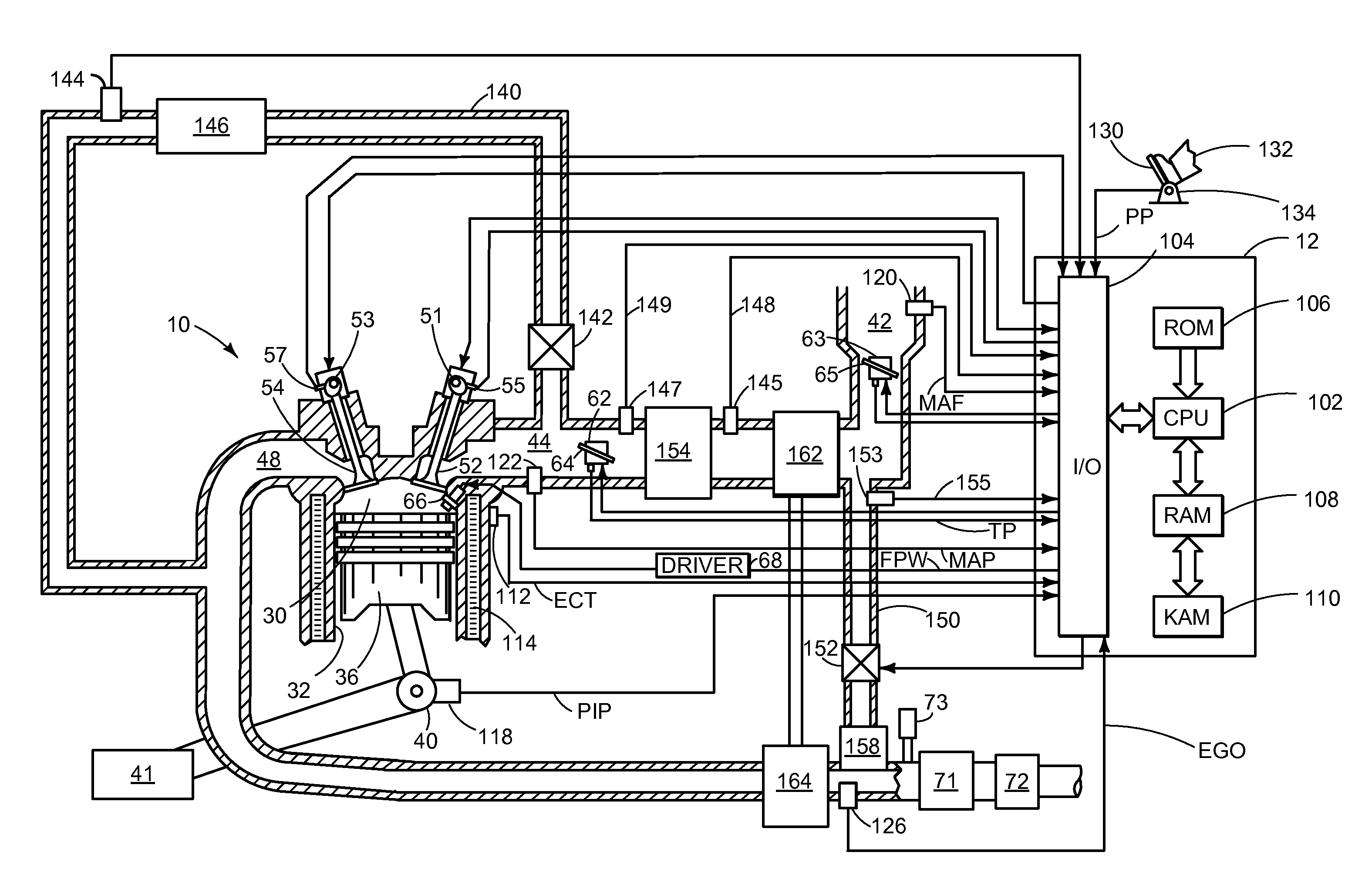
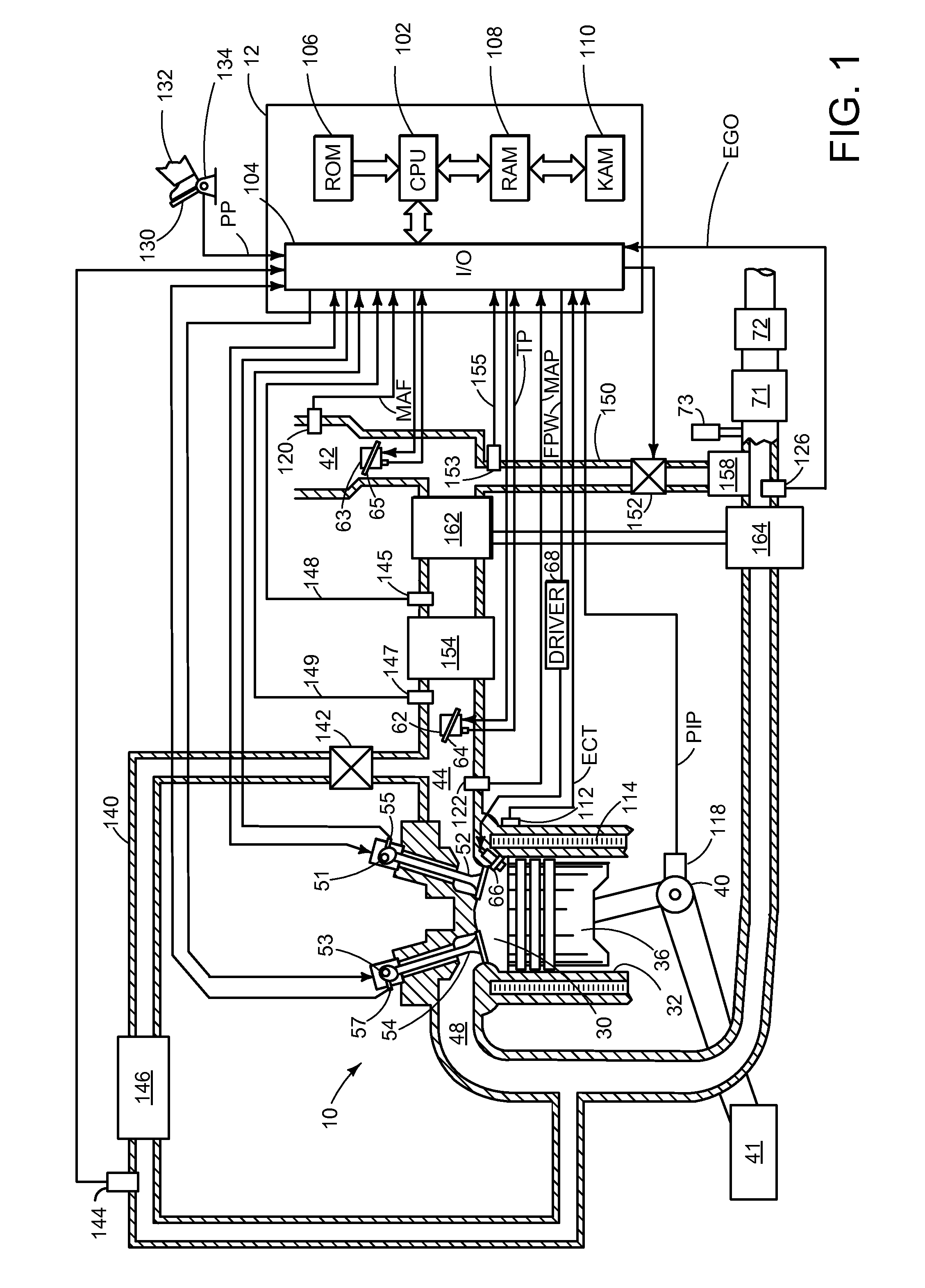
[0015]Referring now to FIG. 1, a schematic diagram of one cylinder of multi-cylinder engine 10, which may be included in a propulsion system of an automobile, is shown. Engine 10 may be controlled at least partially by a control system including controller 12 and by input from a vehicle operator 132 via an input device 130. In this example, input device 130 includes an accelerator pedal and a pedal position sensor 134 for generating a proportional pedal position signal PP. Combustion chamber (i.e., cylinder) 30 of engine 10 may include combustion chamber walls 32 with piston 36 po...


PUM


Abstract

The systems and method described above in the present disclosure allow for regeneration of a diesel particulate filter while a vehicle is in stationary power take-off mode. Described is a method of: during select power take-off conditions, reducing an EGR rate responsive to an indication to regenerate a diesel particulate filter.

Description

TECHNICAL FIELD[0001]The present application relates to control of particulate emissions during stationary power take-off.BACKGROUND AND SUMMARY[0002]Emission control devices, such as diesel particulate filters (DPF), may reduce the amount of soot emissions from a diesel engine by trapping soot particles. Such devices may be regenerated during operation of an engine to decrease the amount of trapped particulate matter. Regeneration is typically achieved by raising the temperature of the DPF to a predetermined level, and ensuring that the exhaust gas entering the DPF is of a certain composition.[0003]Diesel vehicles may further be equipped with exhaust gas recirculation (EGR) systems. EGR systems divert a portion of the exhaust gases back to the intake to cool combustion temperatures and reduce throttling losses, thus improving vehicle emissions and fuel economy. In turbocharged engines, an EGR system may include a low-pressure EGR (LP-EGR) circuit, a high-pressure EGR (HP-EGR) circu...

Claims


Application Information

Patent Timeline
Patent Type & Authority Patents(United States)
IPC IPC(8): F02D41/00F02D41/02
CPCF02D41/0055F02D41/021F02D41/029F02M26/14F02D2200/0812Y02T10/121Y02T10/47Y02T10/40Y02T10/12
Inventor REICH, JEFFKORPICS, FRANK, M.PENNALA, DEANVAN, NIEUWSTADT, MICHIEL, J.PHILION, DAVID, WYNNCAMPBELL, JAMESWEBB, TIMOTHY
Owner FORD GLOBAL TECH LLC
Why Eureka
Try Eureka