Lighting apparatus

a technology of led lighting and lighting modules, which is applied in the direction of lighting and heating apparatus, semiconductor devices for light sources, lighting support devices, etc., can solve the problems of long life of bulbs, frequent replacement, and short service life of bulbs, so as to achieve the effect of prolonging the life of gas-filled tubes such as fluorescent or neon tubes

Inactive Publication Date: 2008-02-12
DIAMOND CREEK CAPITAL LLC
View PDF80 Cites 207 Cited by
  • Summary
  • Abstract
  • Description
  • Claims
  • Application Information

AI Technical Summary

Benefits of technology

[0010]In accordance with a further embodiment, a lighting apparatus is provided comprising a base, an array of LEDs mounted to the base, and a cover configured to cover the array. Power is supplied to the LEDs via an electrical pathway. The cover is mechanically coupled to the base such that attachment of the cover completes the electrical pathway to permit power to flow to the LEDs, and removal of the cover opens the electrical pathway to prevent flow of power.

Problems solved by technology

Such bulbs typically do not have long operating lifetimes and thus require frequent replacement.
Gas-filled tubes, such as fluorescent or neon tubes, may have longer lifetimes, but operate using dangerously high voltages and are relatively expensive.
Further, both bulbs and gas-filled tubes consume substantial amounts of power.
Increased junction temperature may reduce the efficiency and the lifetime of the LED.

Method used


Image

  • Lighting apparatus
  • Lighting apparatus
  • Lighting apparatus

Examples


Embodiment Construction

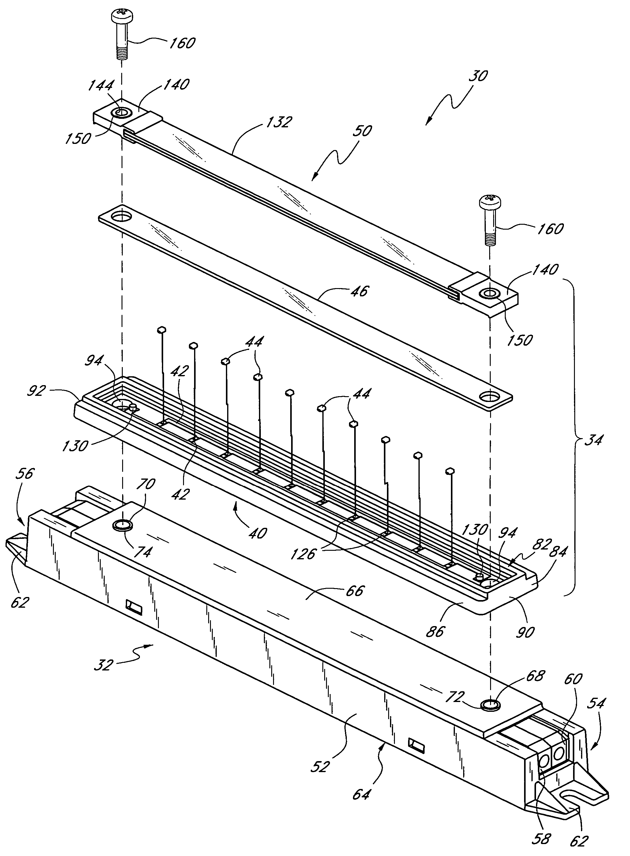
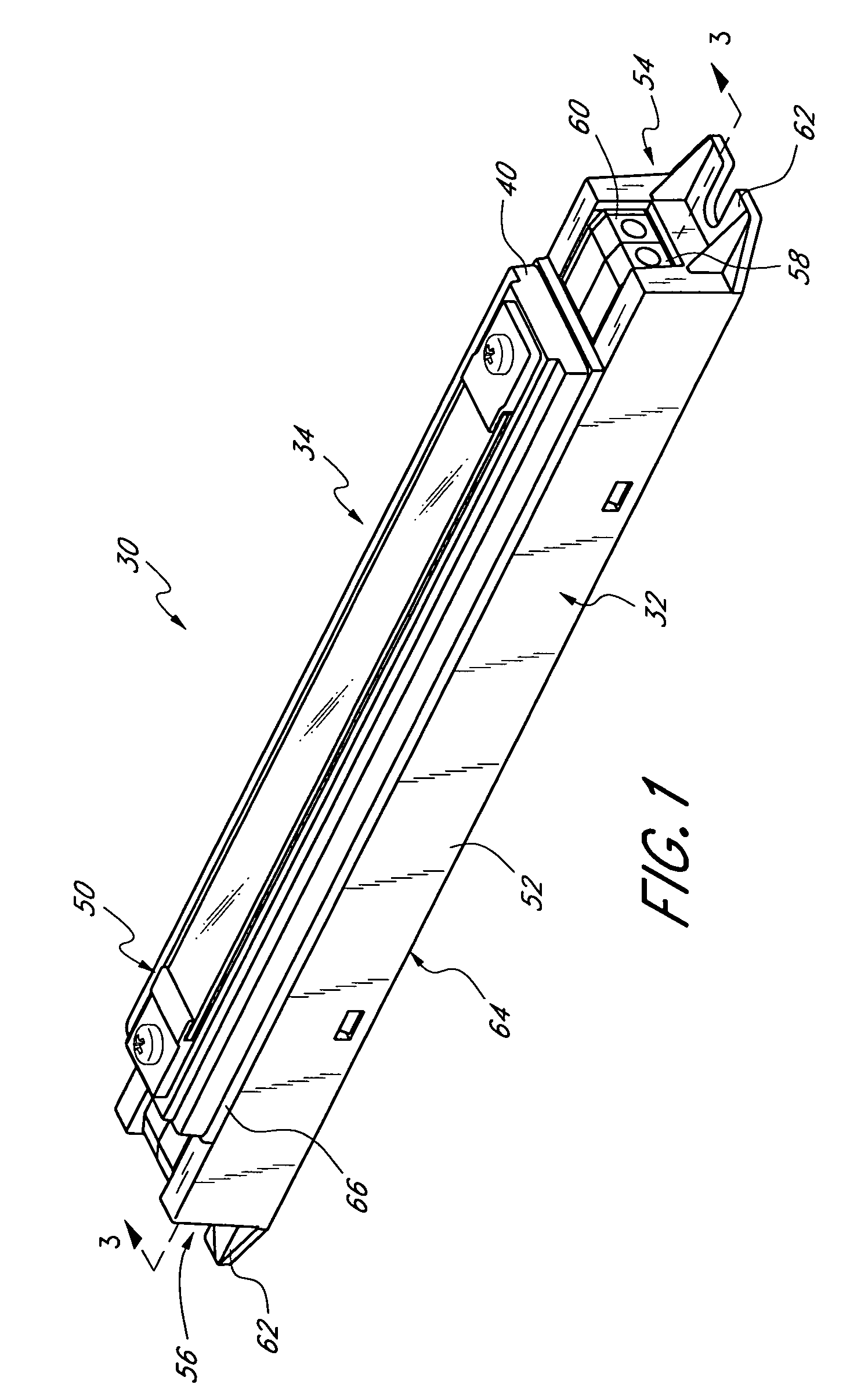
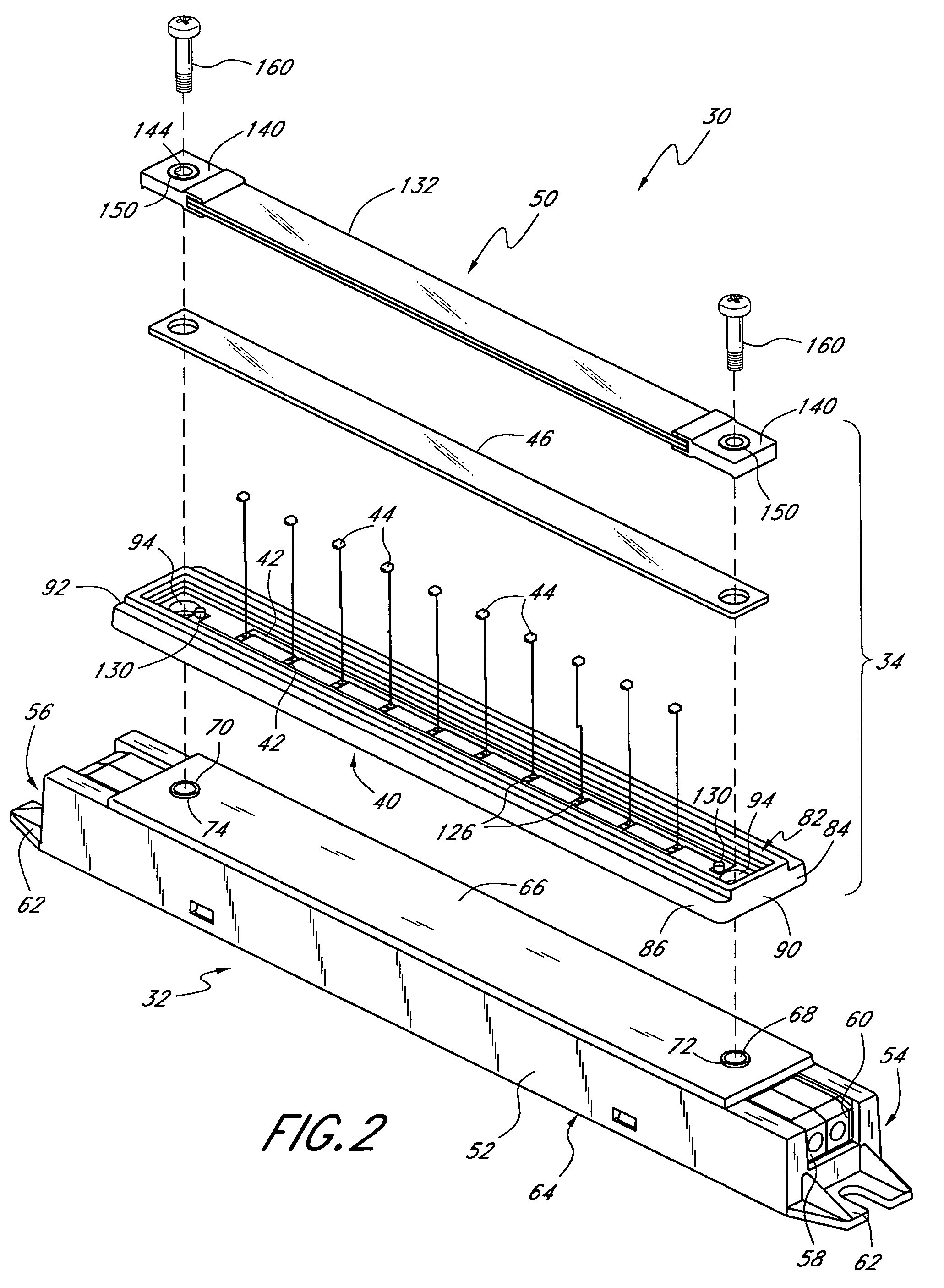
[0041]With initial reference to FIGS. 1-3, an embodiment of a lighting apparatus 30 is illustrated. The lighting apparatus 30 preferably comprises a power module 32 and a light emitting diode (LED) module 34 that are connected to one another. In summary, the LED module 34 comprises a heat conductive base 40 upon which a plurality of electrically conductive traces 42 are disposed. An array of LEDs 44 is mounted on the base 40 and electrically connected to the traces 42. Transmissive material 46 is disposed in and around the LEDs 44, and a cover 50 is placed thereover. The cover 50 preferably comprises a phosphor.

[0042]With continued reference to FIGS. 1-3, the power module 34 comprises an elongate body 52 having a first end 54 and a second end56. Each of the first and second ends 54, 56 include positive and negative connectors 58, 60 that are adapted to connect to flexible conductors such as electrical wire. Further, the first and second ends 54, 56 each include a mounting flange 62 ...


PUM


Abstract

A lighting apparatus is provided including an array of light emitting diodes (LEDs) disposed on a base. The base is configured to move heat away from the array of LEDs to other portions of the base and further to the atmosphere or an adjacent housing. In one embodiment, a native oxide on the base electrically insulates the base from the LEDs. In another embodiment, a cover is removably disposed over the array of LEDs, and removal of the cover prevents electrical energization of the LEDs.

Description

RELATED APPLICATIONS[0001]This application is based on and claims priority to U.S. provisional application Ser. No. 60 / 505,267, which was filed on Sep. 22, 2003 and U.S. provisional application Ser. No. 60 / 546,273, which was filed on Feb. 20, 2004. The entirety of each of the above-referenced applications is hereby incorporated by reference.BACKGROUND OF THE INVENTION[0002]1. Field of the Invention[0003]The present invention relates to light emitting diode (LED) lighting devices and more particularly to LED lighting modules having heat transfer properties that improve the efficiency and performance of LEDs.[0004]2. Description of the Related Art[0005]Most lighting applications utilize incandescent or gas-filled bulbs, particularly lighting applications that require more than a low level of illumination. Such bulbs typically do not have long operating lifetimes and thus require frequent replacement. Gas-filled tubes, such as fluorescent or neon tubes, may have longer lifetimes, but o...

Claims


Application Information

Patent Timeline
Patent Type & Authority Patents(United States)
IPC IPC(8): F21V11/00F21S2/00F21S4/00F21V17/12F21V25/04
CPCF21V29/76F21S4/008F21V3/04F21V15/01F21V23/00F21V25/04F21V29/004F21V31/04F21V29/745F21S2/005F21V17/12F21V21/02F21V23/06F21Y2101/02F21Y2103/003F21S4/001F21S4/10F21S4/28F21Y2103/10F21Y2115/10F21V29/74
Inventor LYNCH, MANUELFRAITAG, LENNYWIJESINGHE, REHANA
Owner DIAMOND CREEK CAPITAL LLC
Why Eureka
Try Eureka