Metal-sheathed composite vehicle axle

a composite, metal-sheathed technology, applied in mechanical equipment, transportation and packaging, rolling resistance optimization, etc., can solve the problem of axle having an ultimate failure load of at least 1800 pounds

Inactive Publication Date: 2008-06-19
BURKETT JERALD S
View PDF21 Cites 14 Cited by
  • Summary
  • Abstract
  • Description
  • Claims
  • Application Information

AI Technical Summary

Benefits of technology

[0017]The primary objective of this invention is to provide a lightweight vehicle axle fabricated utilizing composite technology.
[0019]Still another objective of this invention is to provide a vehicle axle that is stronger than existing metal axles when the end of the axle is subjected to a significant impact.

Problems solved by technology

Additionally, the axle has an ultimate failure load of at least 1800 pounds.

Method used


Image

  • Metal-sheathed composite vehicle axle
  • Metal-sheathed composite vehicle axle
  • Metal-sheathed composite vehicle axle

Examples


Embodiment Construction

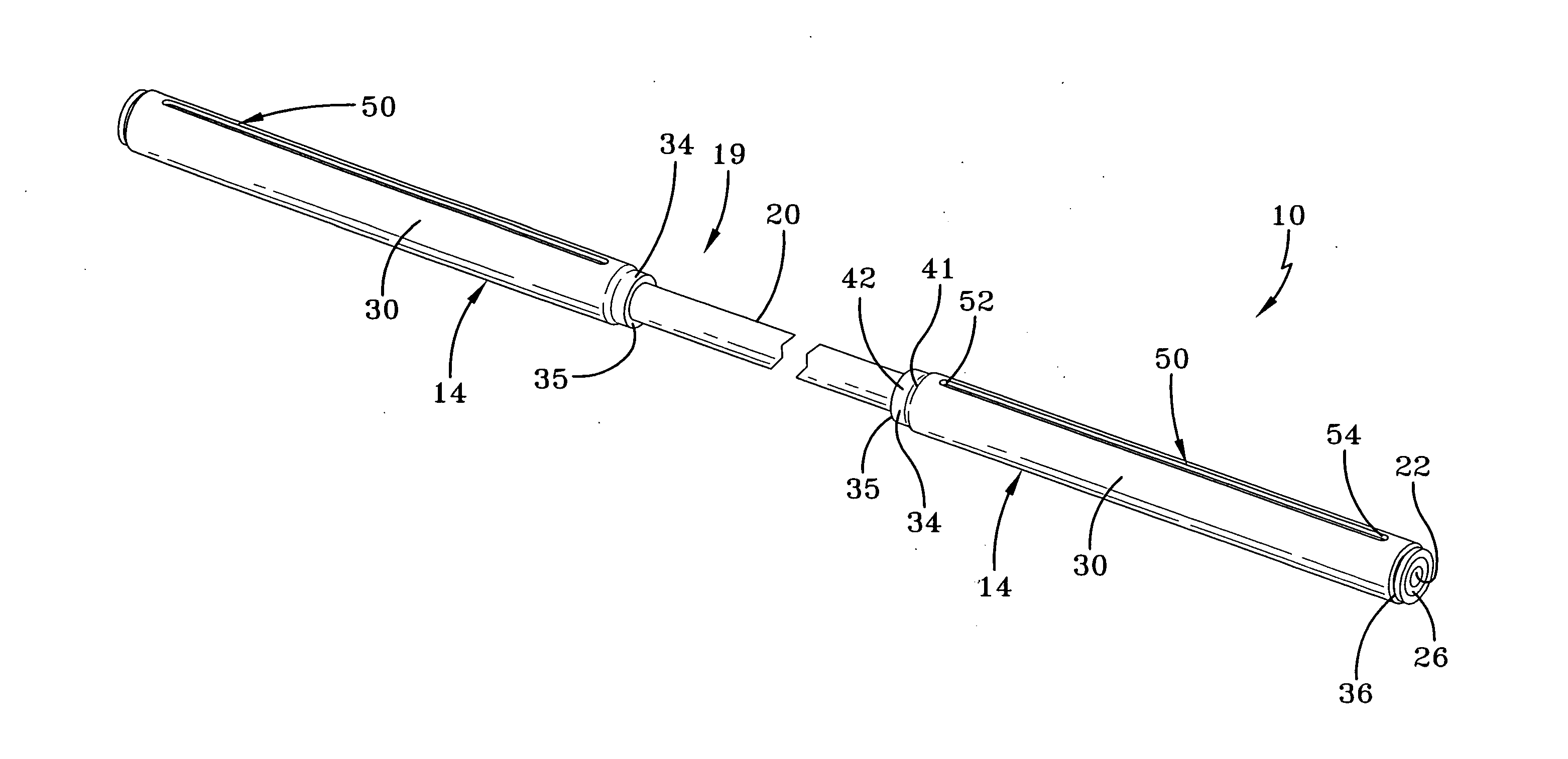
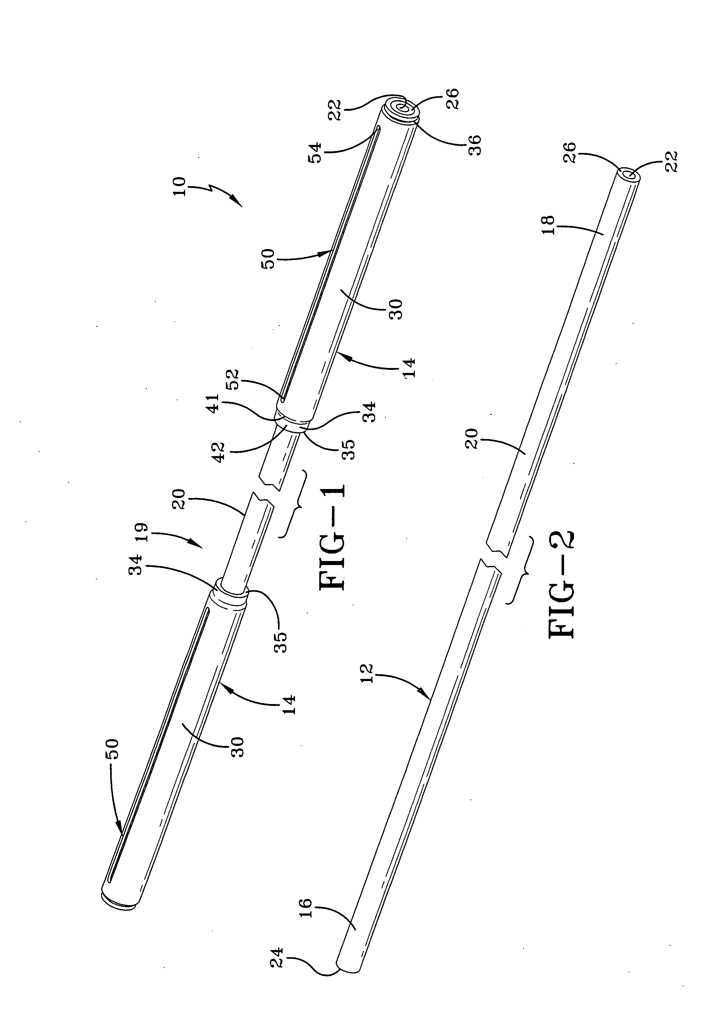
[0028]This invention addresses the above limitations and fully utilizes the potential of composite materials resulting in a lightweight, rugged vehicular axle. Having reference to the drawings, attention is directed first to FIG. 1, which discloses a metal-sheathed composite vehicle axle made in accordance with the invention, designated generally by the numeral 10. Comparison of FIGS. 1, 2, and 6 discloses that the axle 10 of this invention is fabricated having a composite tubular member 12 with a metal sheath 14 attached at the first end 16 and at the second end 18 respectively of the composite tubular member 12. Thus, when assembled the axle 10 features an intermediate axle section 19 located between the metal sheaths at the opposite ends of the axle.

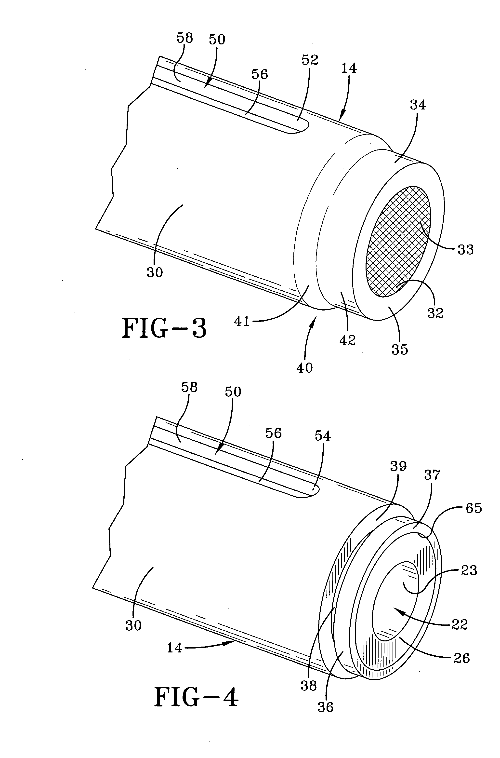
[0029]As can be appreciated from a comparison of FIGS. 2 and 4, the composite tubular member 12 has an outer wall surface 20 and an interior channel 22, with the interior channel having an inner wall surface 23. As is the case with ot...


PUM


Abstract

A vehicle axle formed having a composite tubular member and a pair of metal sheaths spaced apart from one another at opposite ends of the composite tubular member. The composite tubular member has an outer wall surface and an interior elongated channel, with the interior channel having an inner wall surface. The composite tubular member also has a first end wall and a second end wall at opposite ends of the composite tubular member. Each of the metal sheaths has an outer surface, an inner surface, an inner end portion having an inner end portion edge, and an outer end portion having an outer end portion edge. Each metal sheath inner end portion has a transition area, with the transition area having a first area of changing thickness and a second area of a substantially constant thickness. Each of the metal sheaths has stabilization means formed in the outer surface thereof to accommodate a key, with the key when positioned in the stabilization means precluding the rotation of a wheel hub about the axle.

Description

BACKGROUND OF THE INVENTION[0001]1. Field of the Invention[0002]This invention relates generally to vehicle axles, and more particularly, to a composite tubular vehicle axle having each of its opposite ends encased within a tubular metal sheath.[0003]2. Description of the Related Art[0004]This invention is directed to the providing of a metal-sheathed composite axle for use with vehicles. In the manufacture of vehicles, an axle is typically utilized to support the weight of the vehicle, as well as the transferring of the torsional loads of braking and acceleration from the drive train to the wheels of the vehicle, with the wheels being mechanically mounted to the axle in ways well known in the art.[0005]Axles traditionally have been made of metal due to metal's strength; however, metal axles are not without some drawbacks. For example, when used in go karts and midget go karts, a metal axle can be bent by sustaining an impact at its end if the side of the kart crashes into the wall ...

Claims


Application Information

Patent Timeline
Patent Type & Authority Applications(United States)
IPC IPC(8): B60B35/00
CPCB60B35/14B60B2310/316B60B2310/318B60B2360/104B60B2360/36F16C3/02B60B2900/113B60B2900/131B60B2900/311B60Y2200/114B60B2900/111Y02T10/86
Inventor BURKETT, JERALD S.
Owner BURKETT JERALD S
Why Eureka
Try Eureka