Head stack assembly and information recording apparatus

a technology of information recording apparatus and stack assembly, which is applied in the direction of combination recording, data recording, instruments, etc., can solve the problems of reducing energy kuv, affecting the writing of magnetic information, and affecting the accuracy of magnetic information, so as to prevent unnecessary light emission

Inactive Publication Date: 2008-07-03
HITACHI LTD
View PDF3 Cites 27 Cited by
  • Summary
  • Abstract
  • Description
  • Claims
  • Application Information

AI Technical Summary

Benefits of technology

[0025]According to the present invention, an amount of motion relative to the light emitting portion of the head slider, that is, an amount of deflection in the relative position with respect to the light emitting portion, can be measured. Consequently, the amount of light incident on the head slider can be controlled by increasing or reducing the amount of light in correspondence to the amount of deflection, and a specified amount of light may be irradiated onto the medium. Further, the present invention makes it possible to perform, for example, clearance measurement for detecting contact / noncontact between the head slider and the medium in accordance with a variation in or an average of the amount of deflection, and measurement of a variation in a flying attitude, such as pitch angle, of the head slider.
[0026]Further, according to the present invention, by increasing or reducing the amount of light from the light emitting portion by necessity, unnecessary light emission can be prevented, and problems associated with heating in the light emitting portion can be prevented while an appropriate amount of emission light is being secured.

Problems solved by technology

When V is reduced to improve the record density, the energy KuV is reduced, whereby a problem of thermal fluctuation is actualized in that the record information is altered due to thermal energy of about the room temperature.
In this case, however, since the magnitude of a magnetic field strength generatable by the recording head is limited, a problem arises in that an increase in the coercive force Hc disables writing of the magnetic information.
In this case, the amount of heat for reducing the coercive force Hc becomes insufficient, so that writing of the magnetic information is disabled—which leads to a recording error.

Method used


Image

  • Head stack assembly and information recording apparatus
  • Head stack assembly and information recording apparatus
  • Head stack assembly and information recording apparatus

Examples


Embodiment Construction

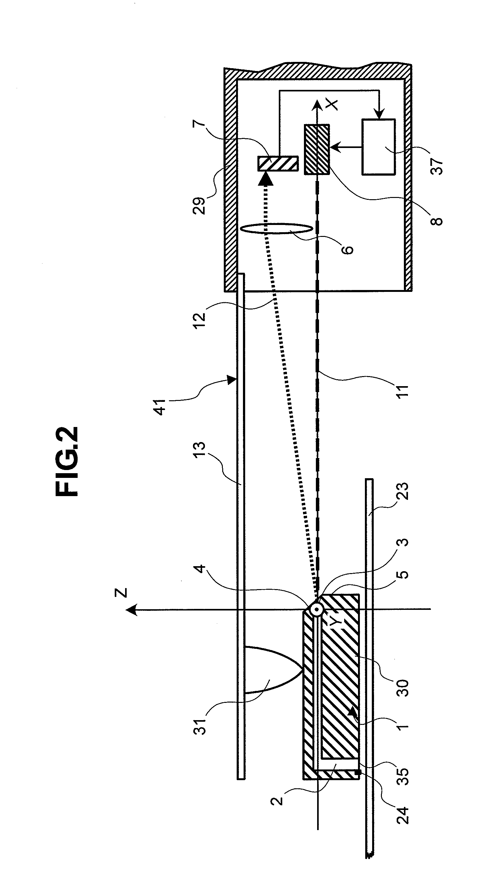
[0038]A heat-assisted magnetic disk drive according to one embodiment of the present invention will be described herebelow with reference to FIGS. 1 to 6. In the respective drawings, like numerals designate like components (or portions) or equivalents thereof.

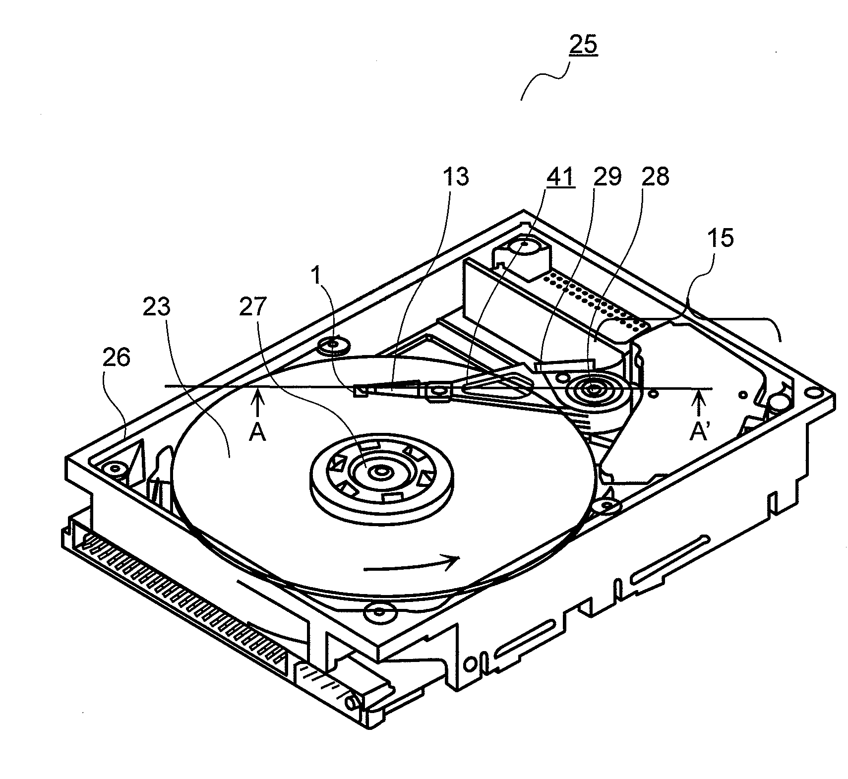
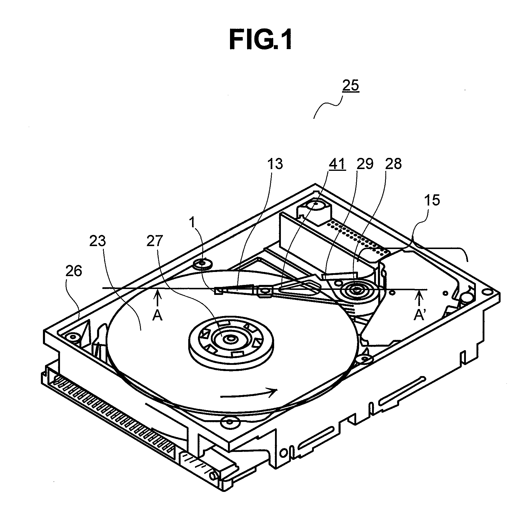
[0039]FIG. 1 is a schematic view showing a heat-assisted magnetic disk drive 25 according to the present embodiment. FIG. 2 is a cross sectional view taken along the line A-A′ of FIG. 1. The magnetic disk drive 25 includes a spindle 27 and pivot 28 fitted to a housing 26; a magnetic disk 23 or a recording medium fixed to the spindle 27; a stack assembly 41 pivotally rotatable about the pivot 28; and a controller (not shown) for controlling recording / playback. The stack assembly 41 includes a head slider 1; a suspension 13 for supporting the head slider 1; and a carriage portion 29 that supports the suspension 13 and that includes a light emitting portion 8, a light receiving portion 7, and a lens 6. The magnetic disk 23 is rota...


PUM

PropertyMeasurementUnit
center angleaaaaaaaaaa
thicknessesaaaaaaaaaa

Abstract

An information recording apparatus includes a medium for recording information; a head slider including a device for writing the information onto the medium and a reflective surface for reflecting light; a light emitting portion for generating emission light toward the reflective surface; a light receiving portion for detecting light reflected on the reflective surface; and a regulating mechanism for adjusting an amount of the emission light from the light emitting portion in a mode of information recording onto the medium in correspondence to a result of the detection.

Description

TECHNICAL FIELD[0001]The present invention relates to a head stack assembly and an information recording apparatus. More specifically, the present invention relates to an information recording apparatus needing to know an accurate position of a head slider, such as a heat assisted information recording apparatus that inputs light to be incident on the head slider, and further relates to a head stack assembly for use in the information recording apparatus.BACKGROUND ART[0002]In recent years, recording devices have continually grown in recoding capacity, and research and development are under way for realizing a device including a magnetic disk drive that has a record density exceeding 1 T bit per an area of 2.54 cm×2.54 cm (one inch square). Increasing the record density of the recording medium requires a reduction of the volume of magnetic grain composing the magnetic disk medium. Now, the magnetic grain volume is represented by V, and a magnetic energy of the grain is represented b...

Claims


Application Information

Patent Timeline
Patent Type & Authority Applications(United States)
IPC IPC(8): G11B5/33
CPCG11B5/1272G11B2005/0021G11B2005/001G11B5/314
Inventor FURUKAWA, MASARUKATO, YUKIO
Owner HITACHI LTD
Why Eureka
Try Eureka