Eureka AIR delivers breakthrough ideas for toughest innovation challenges, trusted by R&D personnel around the world.

Utility Knife with Counter-Reciprocating Blade and Guard

Inactive Publication Date: 2008-07-10
VOTOLATO EARL J
View PDF4 Cites 54 Cited by
  • Summary
  • Abstract
  • Description
  • Claims
  • Application Information

AI Technical Summary

Problems solved by technology

However, the knives in these instances still require manual movement of the user to put the blade guard cover back onto the blade after use.
In all these cases problems arise where the blade is left in an unprotected disposition where it can accidentally cause injury to a user.
Unfortunately, Matin's locking mechanism is external to the housing, which is dangerous because the mechanism is readily subjected to debris that could jam or otherwise interfere with both the locking and unlocking functions.
That operation is dangerous because the pivoted guard can readily interfere with operation of the knife.
The problem still exists that there is no automatic re-locking mechanism, which can still cause injuries to the user.
The mechanism; however, allows some slight backward motion of the pawl, and thus introduces potentially undesirable play in the blade guard.

Method used


Image

  • Utility Knife with Counter-Reciprocating Blade and Guard
  • Utility Knife with Counter-Reciprocating Blade and Guard
  • Utility Knife with Counter-Reciprocating Blade and Guard

Examples


Embodiment Construction

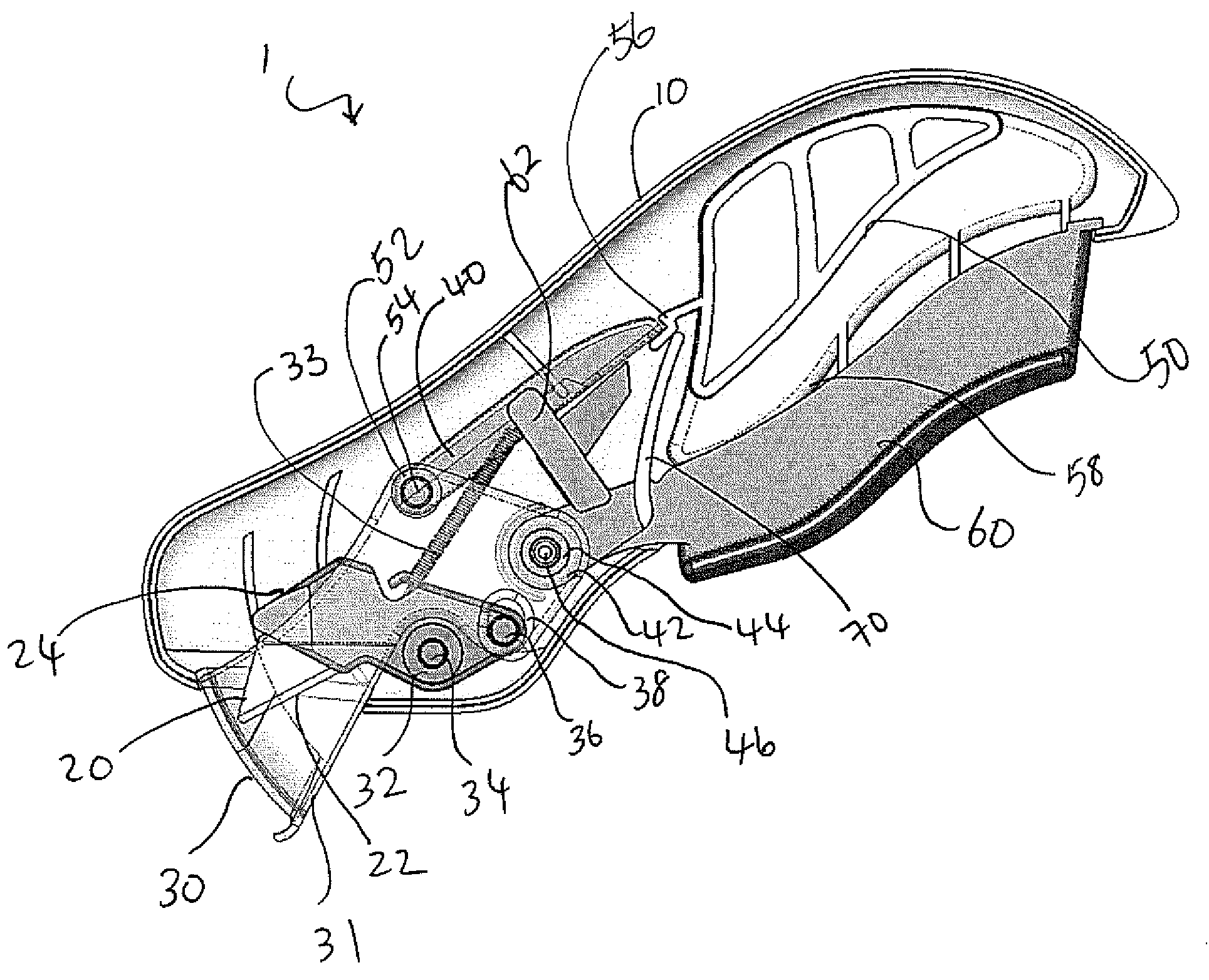
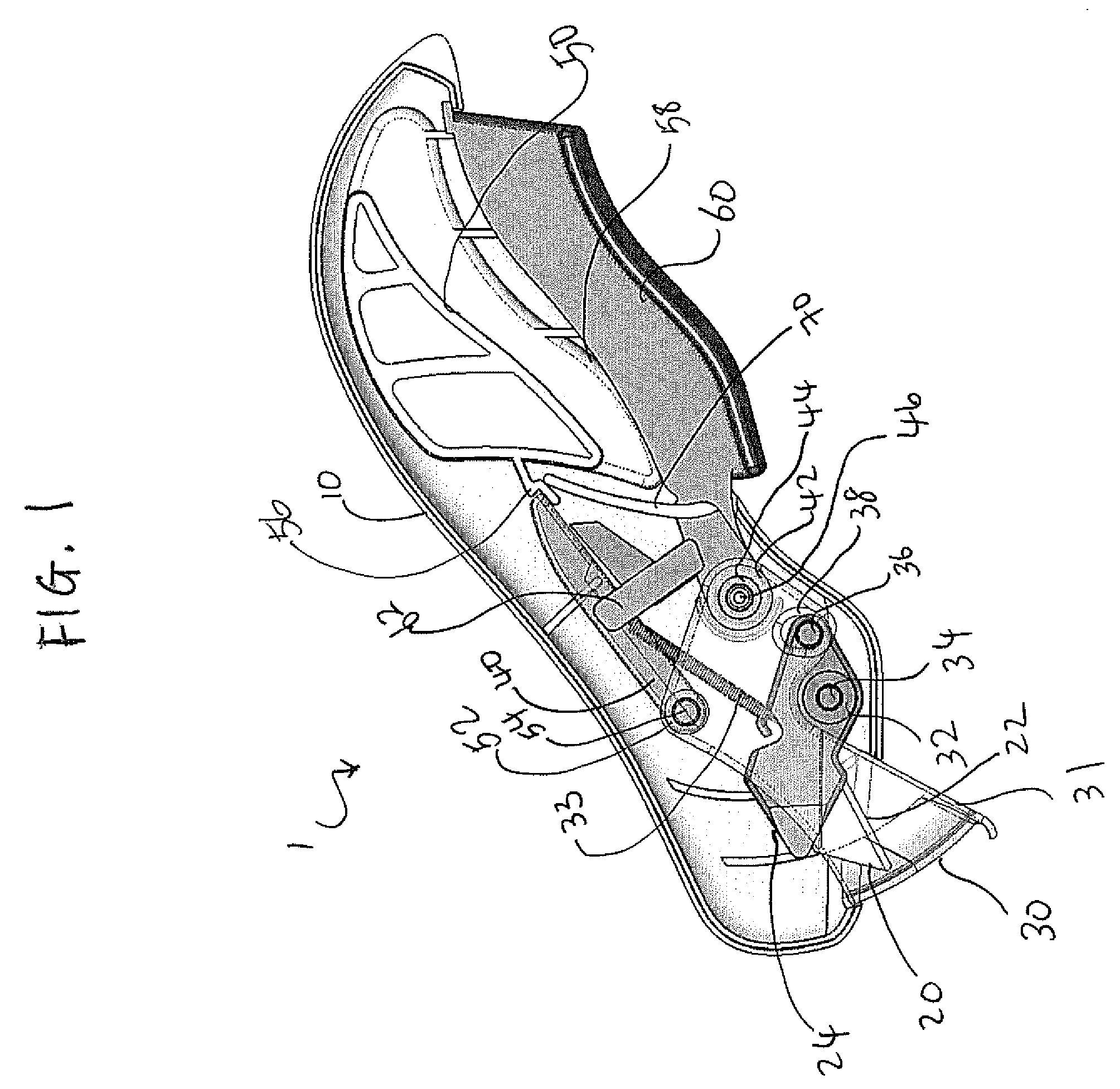
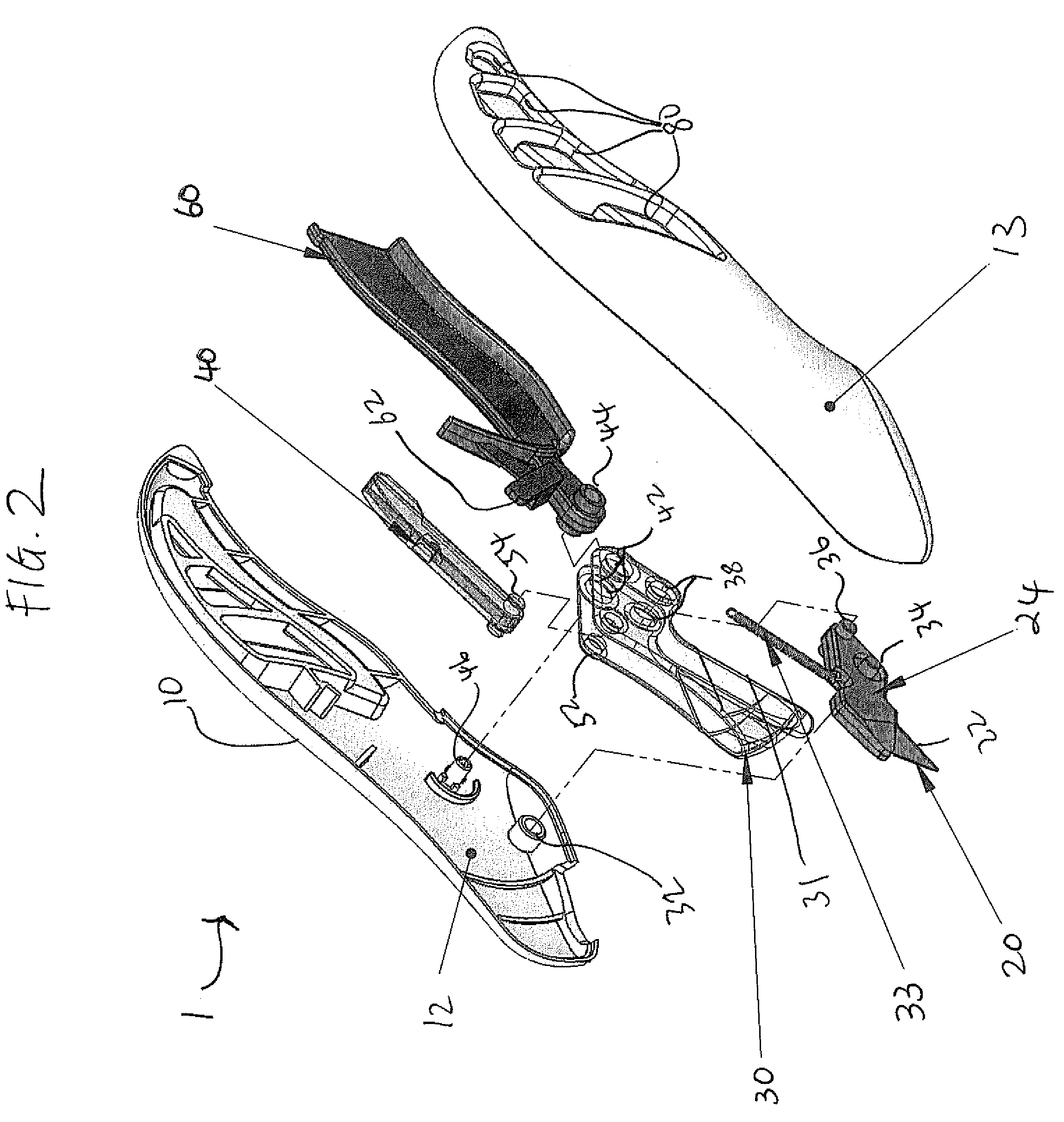
[0018]In FIG. 1 a utility knife 1 generally comprises a housing 10 (only the front portion of which is shown), a blade 20, a blade guard 30, a pawl 40, and a trigger 60.

[0019]Housing 10 is preferably sized and dimensioned to fit comfortably in the hand of a user. Housing 10 can be made of any suitable material, including metals, alloys, and plastics, and can have a hollowed out section (not shown) for storing spare blades. Housing 10 is preferably ambidextrous, but alternatively can include contours that would tend to make the device more acceptable to right or left handed use. Housing 10 pivots about first pivot 32 which allows for housing 10 to be connected to first pin 32 of blade holder 24. Preferably, grooves 80 are located on the outside of housing 10 (as shown in FIG. 2) for better comfort and gripping. Grooves 80 are slots that can either be open or closed, depending on the user's preference.

[0020]Blade 20 is preferably triangular shaped at one or both ends, and has at least...


PUM


Abstract

A utility knife has a counter-reciprocating blade and guard. Preferred mechanism has several components, including a housing, a first pivot that pivotally couples the housing and the blade, and a second pivot that pivotally couples the housing and the guard. Preferably, of the blade and guard reciprocates such that forced retraction of the guard results in forced extension of the blade. During locked position, the guard is in a locked position and a trigger cooperates with the locking mechanism to unlock the guard. The guard can only be unlocked after releasing the trigger to a default position.

Description

FIELD OF THE INVENTION[0001]The field of the invention is utility knives.BACKGROUND[0002]Traditionally, utility knives have a blade either (a) extend external from a blade cover in a fixed position or (b) stored internally in a cover until the blade is manually slid out. Improvements have been made to include a variety of different mechanism to retract or extend the blade mainly for safety reasons. For examples, newer utility knives typically have a sharp cutting blade that can either be retracted into a housing, or released to an operating disposition by movement of a retractable, protective blade guard. However, the knives in these instances still require manual movement of the user to put the blade guard cover back onto the blade after use. In all these cases problems arise where the blade is left in an unprotected disposition where it can accidentally cause injury to a user.[0003]The problem of accidental injury has been long recognized, with numerous solutions being put forward...

Claims


Application Information

Patent Timeline
IPC IPC(8): B26B7/00
CPCB26B5/003
Inventor VOTOLATO, EARL J.
Owner VOTOLATO EARL J
Why Eureka
Eureka Blog
Learn More