Automated cargo loading systems and methods

Inactive Publication Date: 2008-07-10
TRANSBOTICS CORPORATION
11 Cites 121 Cited by

AI-Extracted Technical Summary

Problems solved by technology

Current cargo loading practices are very labor intensive, particularly in circumstances in which a large number of orders are required to be delivered to a number of different customer on the same transport trailer.
Further, because trailers are manually loaded, an automated system is not in pl...

Method used

[0025]Stacking order is determined by the delivery route and is preferably based on a “what is loaded first is unloaded last” principle to improve unloading efficiency. The delivery route is determined by customer locations, delivery priority and product life-span. A customer order, including customer information, may be received through a customer information control system (CICS) transaction sever operable for transmitting customer orders. The orders may be received and processed by the supplier by a transaction interface module within a supplier's main server. Cust...

Benefits of technology

[0006]In various embodiments provided herein, the present invention provides systems and methods for automating truck loading of packaged cargo using system controlled Automatic Guided Vehicles (AGVs) based upon a created loading pattern generated from a cargo delivery route. The system preferably ut...

Abstract

A cargo loading system comprising a control module for coordinating the transportation of cargo from one area to a trailer according to a stacking pattern and delivery route, an AGV control module for controlling the operation and navigation of at least one AGV, and a user interface for inputting commands and receiving outputs into/from the system. A method for loading cargo comprising the steps of providing a cargo loading control module, providing an AGV control module in communication with the cargo loading control module, providing a user interface, communicating cargo loading tasks to an AGV, and transporting cargo from a production area to a trailer in accordance with a stacking pattern and along a dynamic guide path.

Application Domain

Navigation instrumentsRadio wave reradiation/reflection

Technology Topic

EngineeringMarine navigation +3

Image

  • Automated cargo loading systems and methods
  • Automated cargo loading systems and methods
  • Automated cargo loading systems and methods

Examples

  • Experimental program(1)

Example

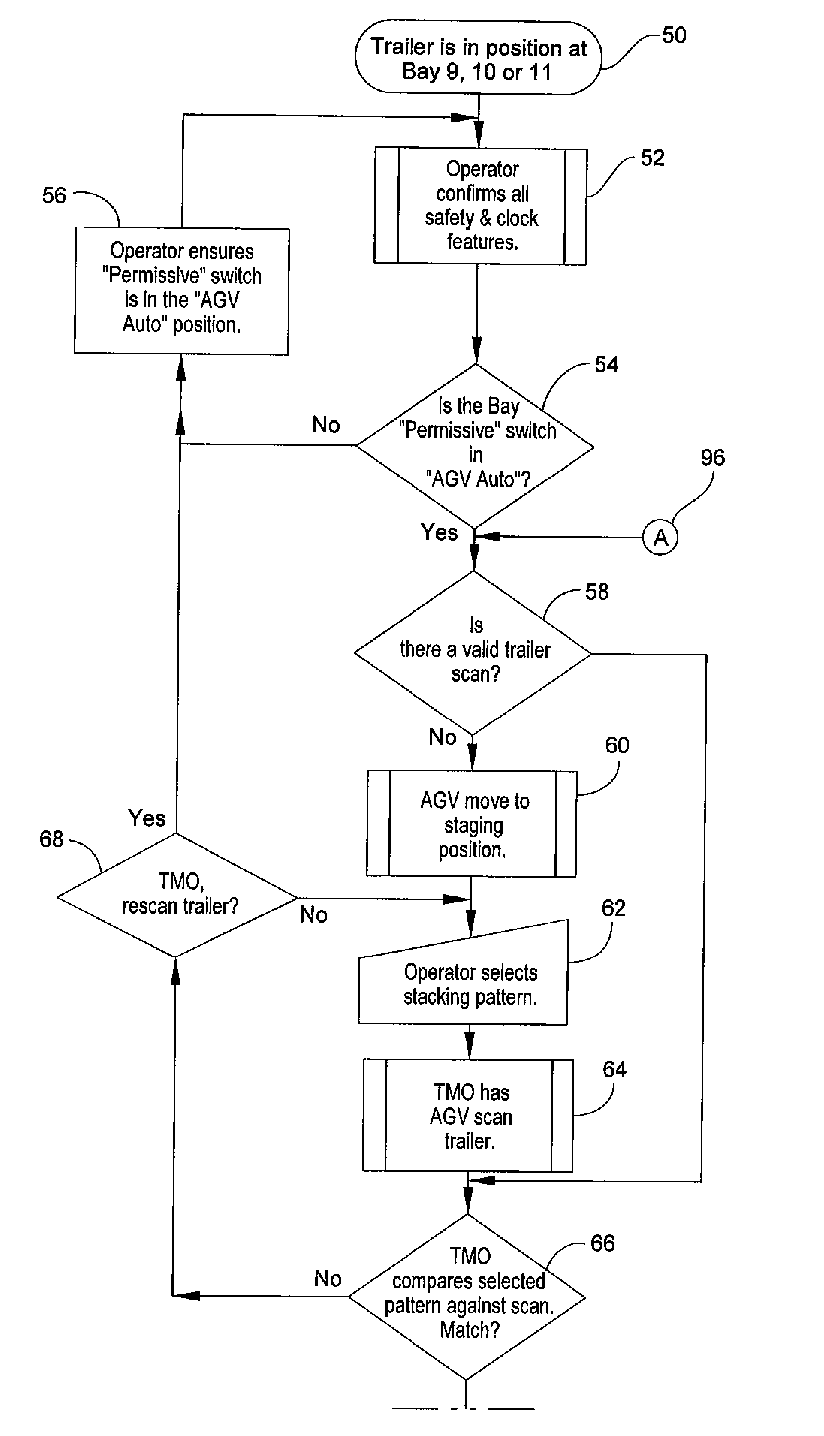
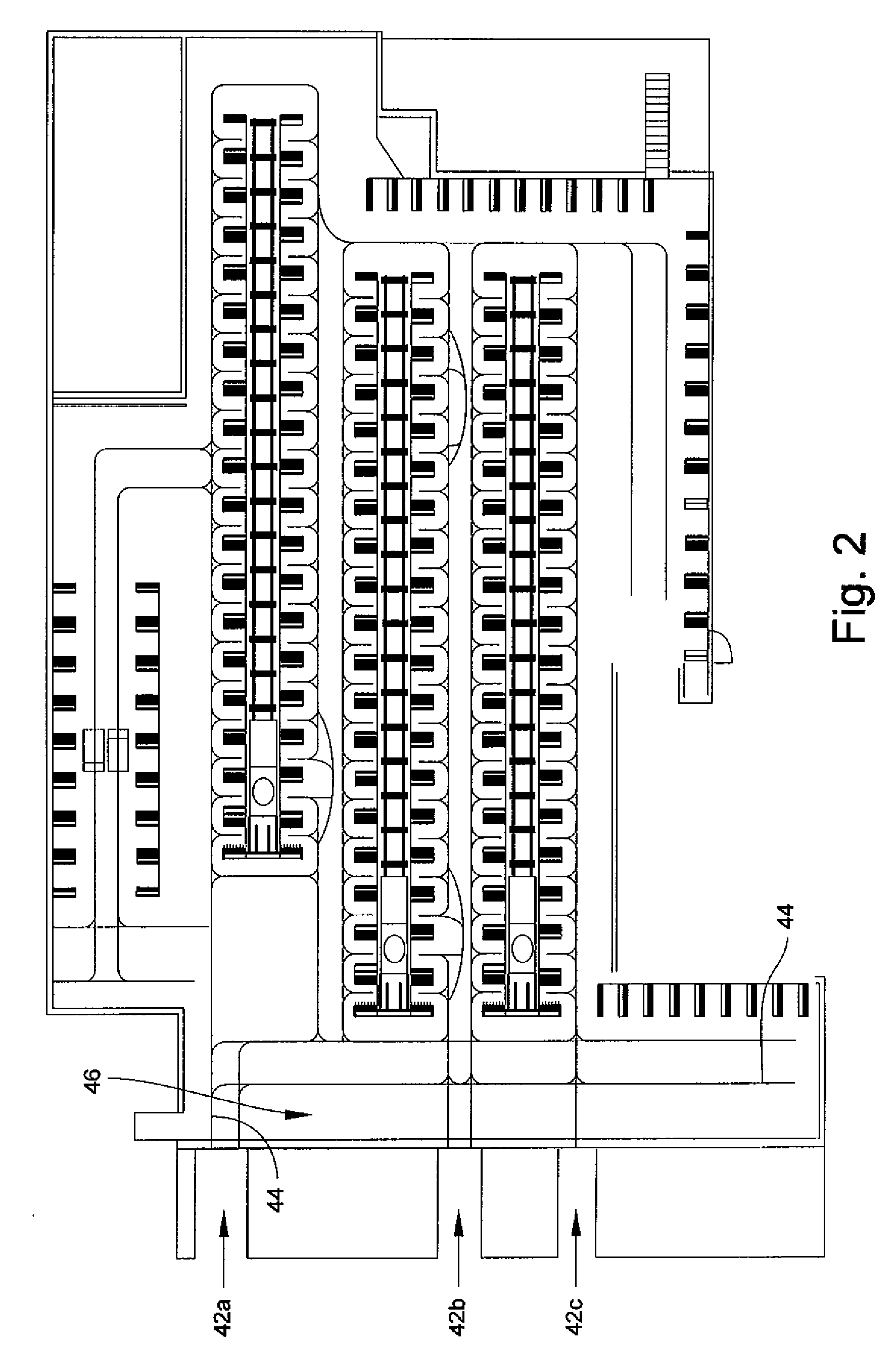
[0016]Referring now to the drawings, systems and methods for generating loading instructions and automating cargo loading are described herein and are illustrated in FIGS. 1-3c. While the systems and methods are described with reference to a particular embodiment in which trailers are loaded at loading bays, the systems and methods may be applied to any cargo loading environment in which cargo is moved from a loading area to a transport. In the exemplary embodiments provided herein, the loading instructions are generated based upon a predetermined delivery route, however, the instructions may be generated based upon other parameters such as delivery priority, weight, and pallet size. As used herein, the term “cargo” generically describes any item loaded onto a trailer, and preferably refers to a packaged pallet.
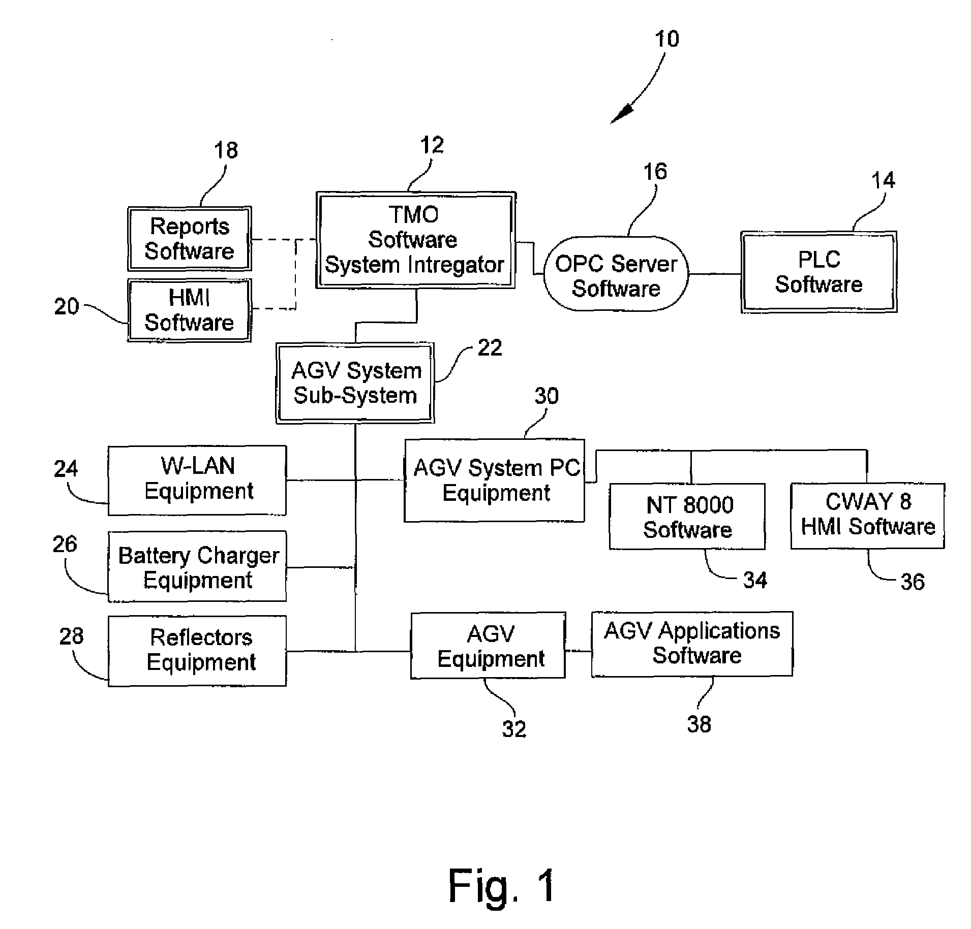
[0017]Referring to FIG. 1, a system diagram illustrating communication between cargo loading modules of the system is shown. Pallets, pre-loaded with a customer-specific selection of products and packaged, are loaded according to a generated or selected stacking pattern and in an order so that the trailer or other transport is unloaded in sequence with a delivery route. The system 10 includes various control modules that reside on computers or servers as software applications. A main control module, referred to herein as the “Transportation Movement Optimizer” (TMO) module 12, or “cargo loading control module”, includes a software application for organizing, maintaining, commanding and recording data of the automated cargo loading system. The TMO module 12 is the software system integrator. The TMO module 12 communicates with a customer's Programmable Logic Controller (PLC) 14 via a server 16. Once the operator has selected the trailer and pattern, the TMO module 12 coordinates the pick-up and delivery of pallets to the designated bay, and validates and maintains the data for each of the bays. Optionally, the TMO module 12 builds and displays reports through a reports module 18 based on desired data, such as throughput numbers, error data and additional real time data. The TMO module 12 also optionally communicates with a user interface module 20 (HMI) for input/output of the system. The user interface module 20 allows users to manipulate the system and allows the system to produce the effects of the users' manipulation. Input/output may be in the form of graphical, textual and auditory information and control sequences.
[0018]The TMO module 12 farther communicates with an AGV sub-system module 22. The AGV module 22 communicates over a wired or wireless local area network (W-LAN) 24 with a plurality of AGV related control modules including: recharging equipment 26 for battery recharging; reflector or guidance equipment 28 for navigation of the AGVs; an AGV system PC 30 operable for input/output into the AGV sub-system; and AGV equipment 32 including one or more AGVs. The AGV system PC 32 includes operating navigational software 34 with environment related information and user interface software 36 for input/output into the AGV system. The AGV equipment 32 includes AGV software applications 38 for control. Communication may be established through tags that have logical names that are pointers to a designated memory address.
[0019]The AGV system controller preferably includes one or more software packages that reside on the PC. One application works in conjunction with the TMO module for AGV movement based on the signals and status of signals that are interfaced to the AGV system, such as the allocation of the AGV, route, route blocking, vehicle movement, order management, and communicating to the AGV. This application interfaces and interacts with the second application for providing for pictorial representation of the AGV system, error logging and system status. The second application is a Graphical User Interface (GUI) that runs on the AGV system controller and provides real time status and condition of the AGV, displays the AGV guide path, pick-up and delivery stations, and 10 statuses. This software application also provides the user with the ability to start orders manually, and maintains a history of events and errors in recursive event logs.
[0020]Referring to FIG. 2, an exemplary environment for practicing the systems and methods of the present invention is shown. The loading zone includes three loading bays, for example loading bay 9 shown at 42a, bay 1042b and bay 1142c, at which trailers (not shown) are parked for loading. AGVs travel along guide paths 44 between the bays and pallet pick-up zones 46. Pallet pick-up zones may be production areas, storage areas, conveyors and packaging areas. The guide paths for the AGVs address AGV traffic issues. Each bay includes guide paths onto a trailer for stacking the cargo according to the instructions. Pallets are preferably scanned for identification and authorization before entering a trailer. While any type of pallet or other container may be used, conventional “one-way” single-use wood pallets or “CHEP” are suitable.
[0021]The TMO module 12 is operable for controlling the system responsible for picking-up loaded pallets of secure, packaged product from a production line or storage area and automatically delivering the cargo to a predetermined assigned trailer occupying bay 942a, 1042b or 1142c in accordance with a stacking pattern. The system is adaptable for use with any type and size of trailer. The system may be pre-loaded with stacking patterns based on trailer identification, size and shape. By way of example, multiple stacking patterns may be allotted for each trailer. The selection of a stacking pattern is the initiation of an “order.” Stacking patterns may also be generated in real-time based on the delivery route and updated as the delivery route changes.
[0022]Referring specifically to FIG. 3a, the automated cargo loading process begins once a trailer is positioned in a designated bay (block 50), such as bay 9, 10 or 11 as shown in FIG. 2. The operator ensures safety and dock features are satisfied (block 52), such as that the appropriate dock is occupied properly, that both the trailer and bay door are open, and that any inhibit switches are in the “AGV automatic” position (block 54). If the bay permissive switch is not in the “AGV auto” position, the system and operator ensures that the permissive switch is put into the auto position (block 56). The operator then once again confirms all safety and dock features (block 52). Once the bay permissive switch is in the auto position, the system scans the trailer identification and determines if there is a valid trailer scan (block 58). Trailer scans are accomplished by an AGV, such as one available from Transbotics Corporation of Charlotte, N.C., moving to a staging position in front of the trailer door (block 60). Once the operator selects a stacking pattern (block 62) the AGV scans the trailer and reports to the TMO module 12 (block 64). The system validates the order by comparing the operator's selected stacking pattern against data from the scanned trailer (block 66). If a trailer scan is not valid, the TMO module 12 requests a trailer re-scan (block 68) once a new trailer is moved into position and the safety and dock requirements are satisfied.
[0023]Referring to FIG. 3b, the automated cargo loading process continues with the TMO module 12 initiating the order and sending an AGV to a production line or other pick-up area (block 70). The AGV follows guide paths to the appropriate pallet, picks-up the pallet, and returns it along guide paths to the appropriate trailer. Once at the trailer, the AGV scans the trailer and reports to the TMO module 12. The TMO module confirms permissive inputs and grants the AGV access to the trailer (block 72). Once access is granted, the AGV moves into the trailer and delivers the pallets to a designated location according to the pre-selected stacking pattern. The TMO module 12 monitors permissive signals (block 74). Throughout the loading process, the TMO module monitors blocks along the vehicle guide paths (block 76). If the AGV is not in a blocked area in the trailer, the AGV exits the trailer (block 78). If the AGV is in a blocked area, the AGV repeatedly sends area signals to the TMO module for interpretation (block 80). Once the signals are determined “good” or “not blocked,” the AGV continues movement (block 82). The AGVs continually send guide path information during movement. If the permissive signals are “bad” or “blocked,” AGV movement is halted and signals are sent again to the TMO module (block 84). Movement resumes after the obstruction is removed.
[0024]Referring to FIG. 3c, the automated cargo loading process continues with the TMO module 12 verifying if the order is complete after each delivery to the trailer (block 86). If the order is determined incomplete after a delivery by an AGV, the TMO module checks the order for the next pallet to be loaded, and if that pallet is still scheduled to be loaded or has been cancelled (block 88). After a delivery order has been entered but not yet filled, an operator has the option of canceling all or a portion of the order in the TMO module (block 90). If the order has not been cancelled, then the AGV is sent to pick up the order and loads it according to the process detailed above (block 92). If the order has been cancelled, loading continues with the next order. Once the order is determined complete, the TMO module signals that the order is complete (block 92). The TMO module then determines if another order is to be placed on the delivery trailer (block 94). If another order is to be loaded, the loading process repeats starting with a valid trailer scan and continues as detailed above (block 96). AGVs travel between the production line and the trailer until the validated stacking pattern is complete. Once the pattern is completed the order is complete. Once an order is complete, the A&V returns to a home base (block 98) where the AGV remains idle, recharges and waits for the next order (block 100). The automated cargo loading process ends (block 102) and begins again upon demand.
[0025]Stacking order is determined by the delivery route and is preferably based on a “what is loaded first is unloaded last” principle to improve unloading efficiency. The delivery route is determined by customer locations, delivery priority and product life-span. A customer order, including customer information, may be received through a customer information control system (CICS) transaction sever operable for transmitting customer orders. The orders may be received and processed by the supplier by a transaction interface module within a supplier's main server. Customer orders are transmitted on demand and are received and prioritized based on delivery date, delivery distance and sales branch, among other factors. The main server includes a database management transaction-SQL module (MS SQL) for database support and may include a pallet building module for optimizing the flow of materials required to build pallets of mixed products. The TMO module 12 may also be located on the main server. The pallet building module may also perform scheduling functions, inventory tracking, to/from moves, and provide a network and AGV interface.
[0026]An AGV used herein may be any type suitable for the requirements of a particular application. One suitable AGV is a forklift style having a three-wheel configuration (one steer and two drive) and quad functionality. The AGV functions by picking-up one pallet at a time from an inventory of pallets or from a conveyor, transporting the pallet to the correct trailer, entering the trailer, and placing the pallet on the floor or on top of another pallet as instructed. The vehicles may be equipped with a laser scanning bumper in the front of the vehicle, flashing lights, battery disconnects and emergency stop buttons. The front bumper may include a laser type S3000 mounted within a protective enclosure. Two detection areas are programmed in the S3000 logic to provide a long distance slow-down range and a short distance emergency-stop (e-stop) range. If the short distance c-stop range is broken, the vehicle enters an e-stop condition. Emergency stop buttons are located on each corner of the vehicle. The buttons must be manually reset before the vehicle re-starts. Activation (depressing the button) causes the vehicle to stop abruptly. An additional reset button may also be activated in conjunction with the emergency stop button reset.
[0027]The AGV preferably uses two components for navigation. First, a navigational laser is positioned and resides on top of a mast mounted on the AGV. This laser has a rotating laser scanner head that triangulates its position with the aid of reflectors strategically placed throughout the area. The scanner transmits a laser beam and receives the reflected beam, from which it measures angles between the reflectors and calculates its actual position. This information is updated many times per second. The position information is transmitted by a communications link such as an RS-422 serial link to the AGV controller. The second navigational component is, for example, a SICK scanner mounted near the top of the mast that navigates the AGV into the trailer. Two safety rated laser scanners are provided on the AGV, one located in the front and the other in the rear. These lasers utilize multiple dynamic fields for triggering the vehicle to slow down or emergency stop. Object detection is accomplished by a scanning laser that gathers information from bar code labels or other identifying indicia applied to the pallets or packaging, and also evaluates the positions of trailers that are docked at one of the loading docks. Dynamic guide paths are created each time the AGV enters the trailer. The combination of SICK guidance, dynamic paths and vision together provide an intelligent way to adapt to the physical location of the trailer without requiring modification to the trailer or loading dock. The AGV is able to overcome differences (within ranges) in trailer alignment to the loading dock in three dimensions. Thus, there may be three different sensors in the automatic guided vehicles: 1) a rotating, mast-mounted laser used for navigation; 2) a stationary “safety” laser also used for navigation; and 3) a 3D sensor that detects existing cargo.
[0028]In preferred embodiments, the trailer or other container to be loaded is stationary within a loading bay and its position detected by and known by the navigation module of the system. Loading instructions are preferably generated in part from the known position of the trailer. The AGVs scan the interior of the stationary trailer to determine the trailer's location and reveal whether other cargo in the form of pallets is already present and loaded. The loading instructions are capable of accommodating the existence of previously loaded cargo.
[0029]As stated above, the systems and methods described herein may be used in conjunction with a pallet building module that includes pallet building preparation and system control modules including, but not limited to, a production control interface module, a pallet controller module, a website management system controller module, and a logistics controller module. These modules communicate through an internal communication system to pallet building and transportation modules including, but not limited to, the automatic guided vehicle system controller module, a robot system controller module, a fork lift system controller module, and a conveyor system controller module. Upon receipt of a customer order, the pallet building module processes the order, runs programmed pallet building logic, begins a source product replenishment process, and begins the pallet building process.
[0030]Orders may change from the time that they are received to the time that they are loaded. Changes may include product type, quantity, and desired delivery date, among other customer requests. Assigned delivery priority may also change during an order life cycle based upon the customer changes, source items in stock and delivery routes, among others. Updated orders are processed and re-prioritized and new delivery routes are generated.
[0031]While automated cargo loading systems and methods have been described above with reference to particular embodiments and examples, it is intended that various details of the invention may be changed without departing from the scope of the invention. Furthermore, the foregoing description of the preferred embodiment of the invention and best mode for practicing the invention are provided for the purpose of illustration only and not for the purpose of limitation.

PUM

no PUM

Description & Claims & Application Information

We can also present the details of the Description, Claims and Application information to help users get a comprehensive understanding of the technical details of the patent, such as background art, summary of invention, brief description of drawings, description of embodiments, and other original content. On the other hand, users can also determine the specific scope of protection of the technology through the list of claims; as well as understand the changes in the life cycle of the technology with the presentation of the patent timeline. Login to view more.
Why Eureka
Try Eureka