Vehicle detection system

a detection system and vehicle technology, applied in the field of vehicles, can solve the problems of inability to energize the track relay, limiting the number of grade crossings to have merely passive warning systems, and high cos

Inactive Publication Date: 2008-07-17
CENT SIGNAL
View PDF76 Cites 55 Cited by
  • Summary
  • Abstract
  • Description
  • Claims
  • Application Information

AI Technical Summary

Problems solved by technology

Historically it has been cost prohibitive to include active warning systems at every grade crossing, thereby limiting many grade crossings to have merely passive warning systems.
As a result, the track relay cannot be energized if a train occupies the rails between the track battery and the track relay.
Common causes of track circuit failure with typical railroad fail-safe circuits that may interrupt the current path include broken rail, broken wire connections between the battery or relay and the rail, broken rail joint electrical bonds, and failed battery power.
As a result the rate of speed for the roadway vehicles is dramatically reduced, and often stopped.
The slow rate of speed and common stoppage of traffic commonly is not accurately detected by certain magnetic field detectors.
However, a major disadvantage to the use of known loop detectors is that they do not reliably detect slow-moving objects passing through the magnetic field.
Due to the size and mass of trains they do not have the ability to accelerate quickly from a stopped position.
One of the inherent problems associated with certain magnetic field detector is that a requisite minimum rate of speed prevents detection of slow moving objects.

Method used


Image

  • Vehicle detection system
  • Vehicle detection system
  • Vehicle detection system

Examples


Embodiment Construction

[0019]In the following detailed description, references are made to the accompanying drawings that form a part thereof, and are shown by way of illustrating specific embodiments in which the invention may be practiced. These embodiments are described in sufficient detail to enable those skilled in the art to practice the invention, and it is to be understood that other embodiments may be utilized and that structural, logical and electrical changes may be made without departing from the spirit and scope of the present invention.

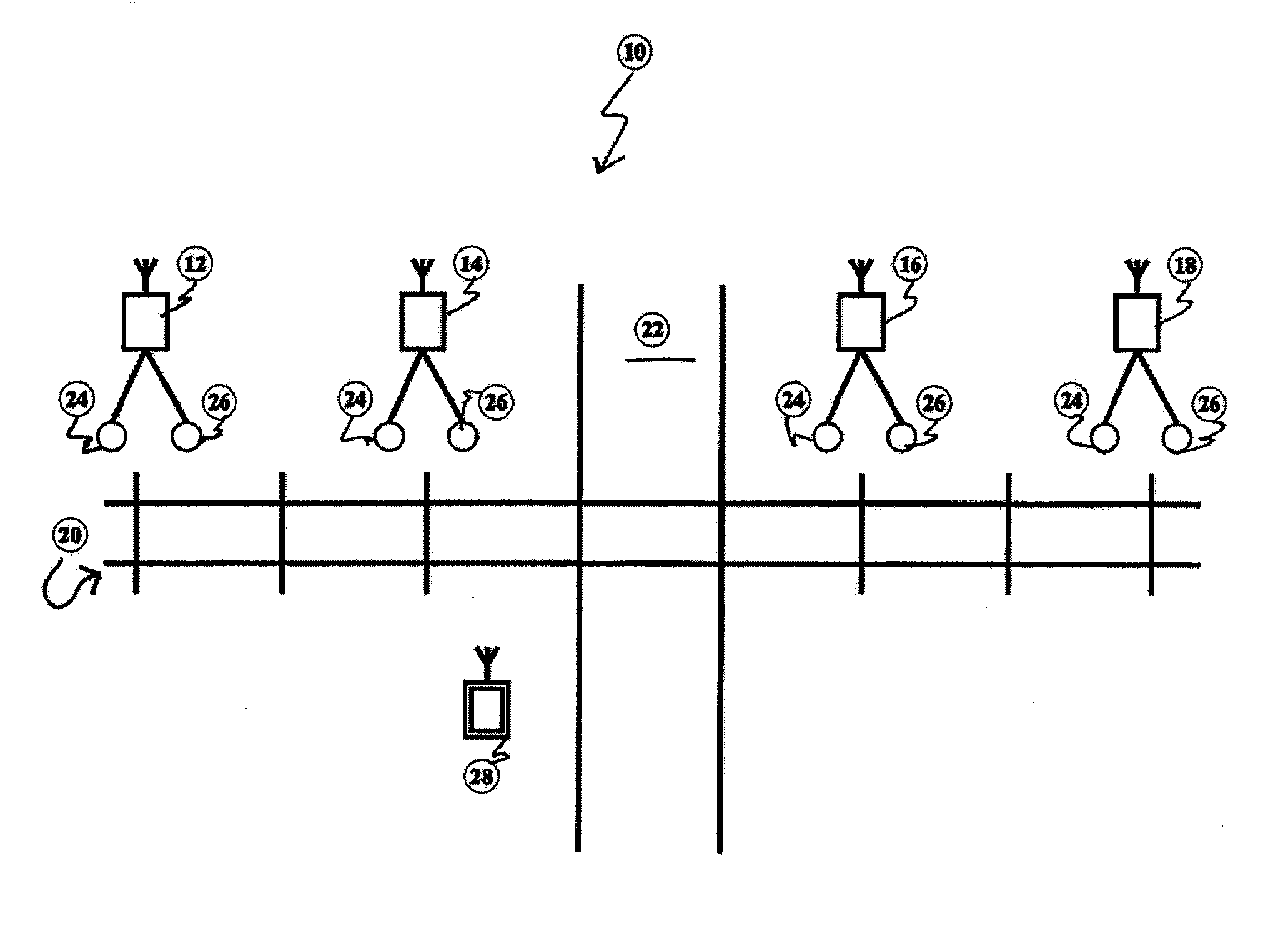
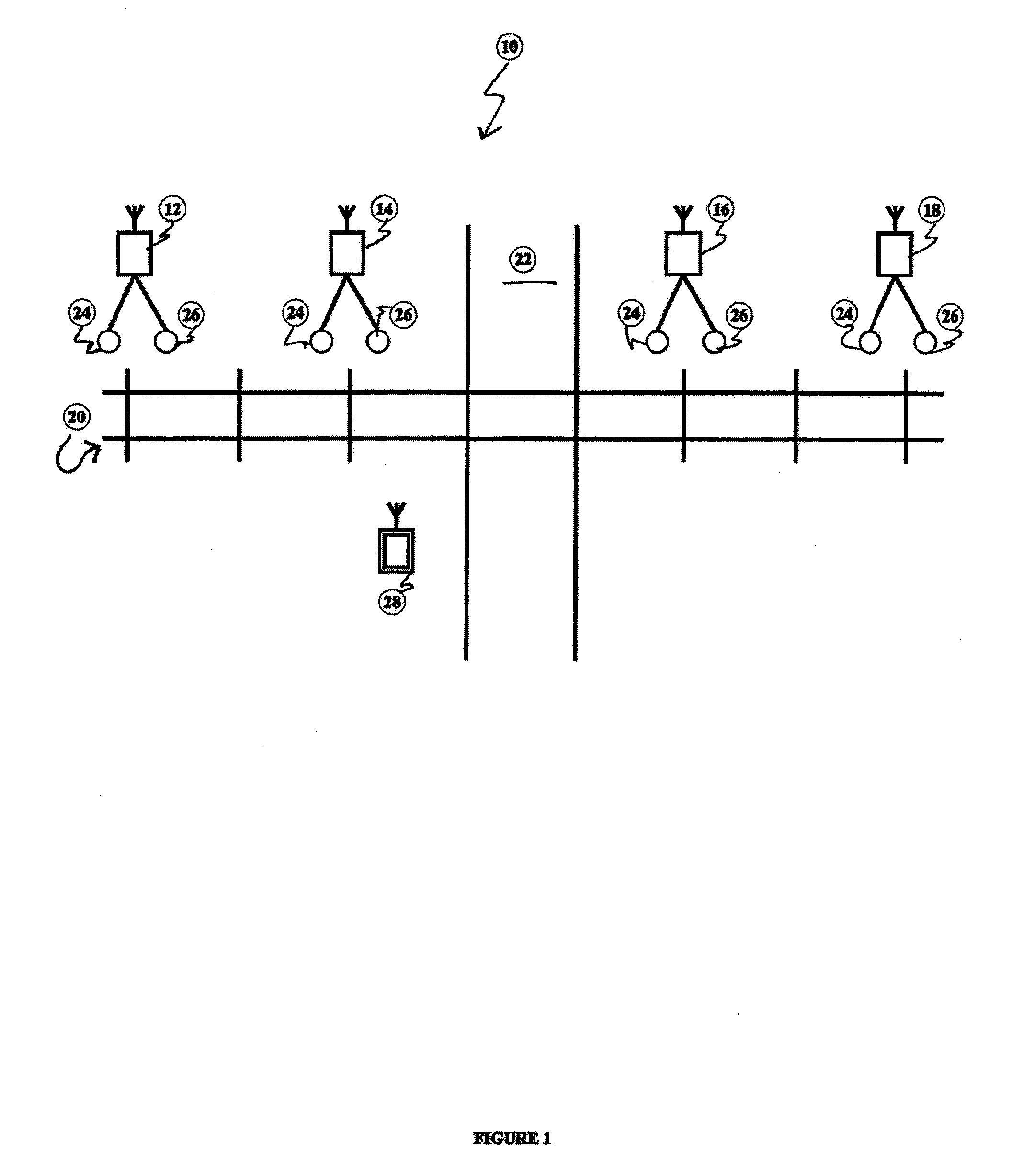
[0020]An embodiment of a vehicle detection system 10 is represented in FIG. 1. The system 10 includes sensor devices 12, 14, 16, 18, each sensor 12, 14, 16, 18 has a pair of sensor nodes 24, 26, and a control processor 28. Each of the sensor nodes 24, 26 is placed in proximity to the railway track 20, which crosses a roadway 22. Data from the sensor nodes 24, 26 is communicated through wireless transmission and reception with the control processor 28. The wire...


PUM


Abstract

An vehicle detection system is provided for tracking, detecting, and monitoring vehicles. The system and methods of the present invention are suitable for on track and roadway vehicles. In particular the present invention provides an improved and cost effective system and methods for tracking, detecting and monitoring locomotives and on track vehicles.

Description

CROSS REFERENCE TO RELATED APPLICATIONS[0001]This application claims priority to U.S. Provisional Application Ser. No. 60 / 871,609, filed Dec. 22, 2006, U.S. Non-provisional application Ser. No. 11 / 964,606 filed Dec. 26, 2007, PCT Application Serial Number PCT / US07 / 88849 filed Dec. 26, 2007, U.S. Provisional Application Ser. No. 60 / 884,930, filed Jan. 15, 2007, each application is fully incorporated by reference herein.[0002]The present invention relates to systems for detecting and processing information generated by moving objects. More specifically various embodiments of the application relate to systems and methods for detecting and processing information generated by on-track vehicles including locomotives, train cars of all types and railroad maintenance and inspection vehicles.BACKGROUND OF THE INVENTION[0003]Methods for warning motor vehicle operators at highway-rail grade rail crossings are either passive or active. Passive warning methods at public crossings are often requi...

Claims


Application Information

Patent Timeline
Patent Type & Authority Applications(United States)
IPC IPC(8): B61L1/00
CPCB61L29/28B61L29/22B61L29/282
Inventor ASHRAF, AHTASHAMBALDWIN, DAVID
Owner CENT SIGNAL
Why Eureka
Try Eureka