Embroidery Machine

a technology of embroidering machine and presser foot, which is applied in the direction of embroidering machine, feeder, textiles and paper, etc., can solve the problems of constant damage to the contact between the needle bar support case b>4/b> and the presser foot holder b>6/b> producing noise upon impa

Inactive Publication Date: 2008-09-11
SUSR PRECISION CO LTD
View PDF5 Cites 35 Cited by
  • Summary
  • Abstract
  • Description
  • Claims
  • Application Information

AI Technical Summary

Benefits of technology

[0024]The present invention has been made to solve the foregoing problems with the prior art, and therefore the present invention provides an embroidery machine, which has a separate drive structure for a presser foot, so that the stroke or the lower end point of a presser foot can be freely changed and the moving track of the presser foot can be freely generated.

Problems solved by technology

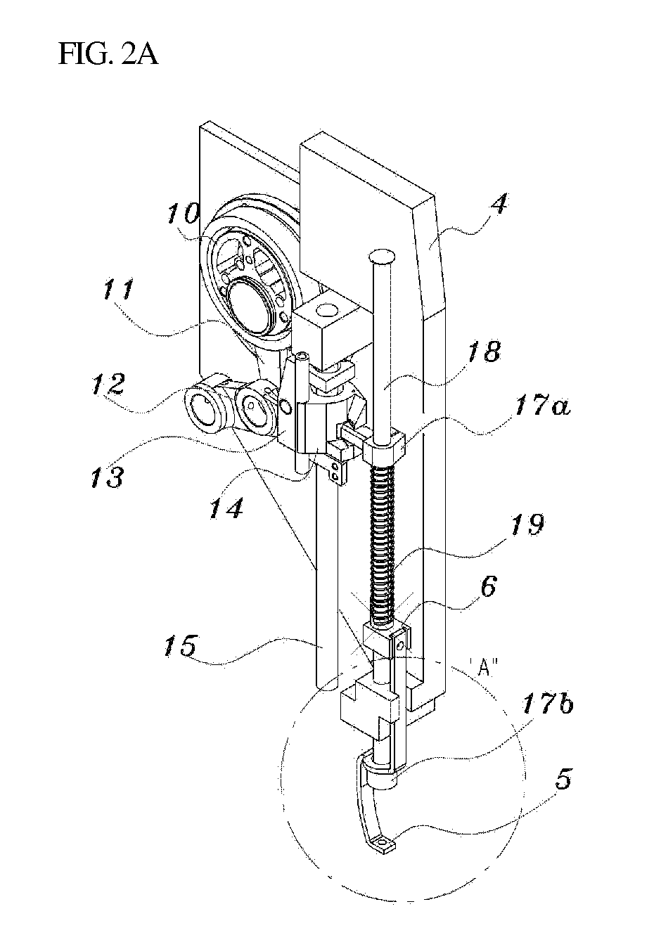
Accordingly, there are problems in that an operator or a user cannot freely change some parameters of the presser foot 5, such as the stroke (i.e., the distance between the top dead point and the bottom dead point), the bottom dead point, and the moving track.
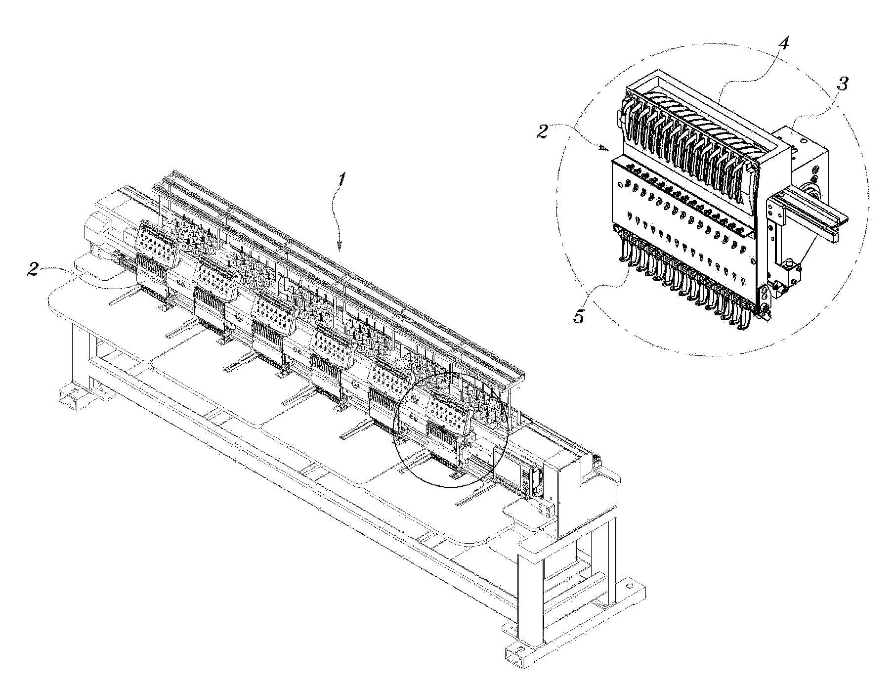
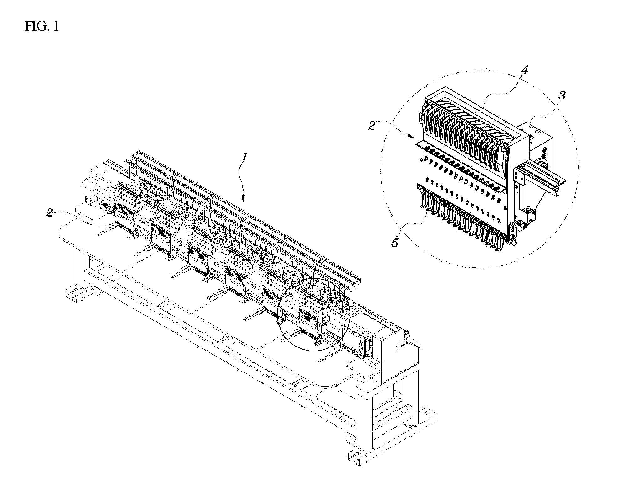
However, the contact between the needle bar support case 4 and the presser foot holder 6 produces noise upon impact.
Furthermore, since contact is frequent, the presser foot holder 6 is constantly vulnerable to damage.

Method used


Image

  • Embroidery Machine
  • Embroidery Machine
  • Embroidery Machine

Examples


Embodiment Construction

[0051]Hereinafter, an embroidery machine according to the present invention will be described more fully with reference to the accompanying drawings.

[0052]FIG. 3 is a perspective view illustrating a sewing head having a drive structure for a presser foot according to an embodiment of the present invention, FIG. 4A is a perspective view illustrating the drive structure for a presser foot according to the present invention, FIG. 4B is an expanded view of part “B” of FIG. 4A, seen from one direction, FIG. 4C is an expanded view of part “B” of FIG. 4A, seen from the other direction, and FIG. 5 is a side elevation view illustrating the drive structure for a presser foot according to the present invention, in the mounted position.

[0053]Referring to FIGS. 3 to 5, the embroidery machine of the present invention is constructed in such a fashion that each of the needle bar and the presser foot is actuated by an independent drive mechanism.

[0054]In the drive structure for a presser foot, as sh...


PUM


Abstract

An embroidery machine includes a sewing arm having an upper shaft for providing a driving force, a needle bar support case, which is assembled to a front portion of the sewing arm so as to be laterally movable, a needle bar provided in a needle bar support case, the needle bar having a needle at a lower end thereof and vertically carrying the needle using a rotation driving force of the upper shaft, and a presser foot, which is provided in the needle bar support case so as to be vertically movable, characterized in that each of the needle bar and the presser foot is operated by an individual drive mechanism. The presser foot is separately driven by its own drive source, independent of the drive source of the needle bar.

Description

BACKGROUND OF THE INVENTION[0001]1. Field of the Invention[0002]The present invention relates to embroidery machine, and more particularly, to an embroidery machine, in which a presser foot (a cloth pressing member) can be separately driven by its own drive source, independently from the drive source of a needle bar.[0003]2. Description of the Related Art[0004]Generally, an embroidery machine is a biaxial positioning control machine in which an embroidery stitch frame for fixing fabric undergoes horizontal motion in x-axis and y-axis directions while a needle bar thereof moves up and down.[0005]Since this embroidery machine does needlework while the embroidery stitch frame, fixing the fabric, is transferred in x-axis and y-axis directions, the precise and constant-speed movement of the embroidery frame has a close relationship to the quality of an embroidered pattern.[0006]Accordingly, a drive source of the embroidery machine, which transfers the needle bar in vertical directions an...

Claims


Application Information

Patent Timeline
Patent Type & Authority Applications(United States)
IPC IPC(8): D05C11/06D05C3/02
CPCD05B19/12D05B29/02D05C9/20D05B55/14D05C3/02D05B29/12D05C11/06
Inventor PARK, CHAN SOO
Owner SUSR PRECISION CO LTD
Why Eureka
Try Eureka